Meshing a dam
Introduction
In the software several meshing commands are available. The combination of these commands provides various meshing strategies.
Here we will show an example coming from a dam with several parts requiring special attention:
The main dam part, which is a very smooth surface.
Some rocks on each sides of the dam, which represent quite a rough surface.
Some very sharp edges on the side of the dam walls.
Some writings of the top of the dam.
Note that in the Samples there is another example based on a point cloud of the Samothrace victory (famous statue in the Louvre museum in Paris) which is a very noisy point cloud representing a smooth surface. Then, a different strategy is used in the case of this statue.
Exercise overview
In this exercise, we will see how to mesh point cloud(s).
Manually clean point cloud(s).
Making a first mesh to see what happens and decide the strategy to be used.
Making a regular mesh at a certain level of detail.
Filling some holes and open contours.
Exploding a mesh into several pieces.
Improving the accuracy of the mesh in certain zones.
Deleting some triangles in a mesh.
Re-meshing locally the edges so that they look sharp.
Locally smooth noisy parts.
Extract some features from the model: cylinder.
Create a freehand section.
Make some sections along a curve.
The file used in this tutorial is DamRock. 3dr
Cleaning the cloud
Select all the clouds that you see on the screen with a rectangle from right to left + SHIFT key (except Cleaned Cloud).
Launch the command Clean / Separate.
Appropriately orient the view and click on the contour around the points that you want to delete.
Remove the points with the bin icon.
If necessary, select another group of noisy points.
When your cleaning is finished, click OK.
To continue the exercise, use Cleaned Cloud, which has already been cleaned.
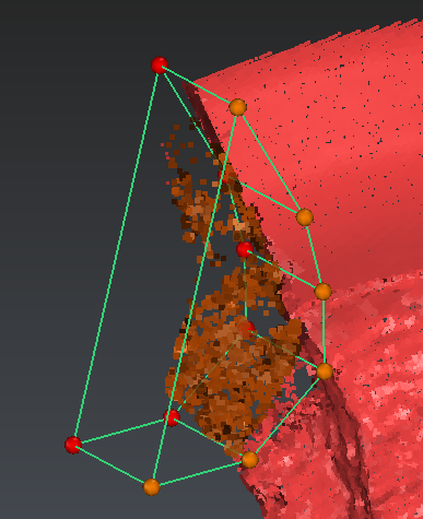 Figure 1: With the command Clean \ Clean / Separate, you can select some points within a polygon. Control points are available to transform the polygon in a box.
Making a first mesh to see what happens
Generally when opening a new cloud, it is difficult to know what the meshing parameter ideal values are. When you launch the command 3D Mesh, the software computes parameters for you to get a result in less than 30 seconds regardless of the size of the point cloud. These default parameters usually give good results but sometimes need to be adjusted according to your model and your expectations.
Select Cleaned Cloud.
Launch the command 3D Mesh.
Select Regular sampling, and change the default parameter and enter 1.5 for the Average distance between points.
Select Hole detection and keep the computed value for Triangle size.
Click OK. The first mesh should arrive in less than 5 seconds.
When the mesh is on the screen, right click to select the Flat representation. The flat rendering is a mode which suppresses the artifact or smoothing effect coming from the graphics card.
Note that you can swap the selected mesh normal typing the I key.
You can display Cleaned cloud over the mesh to make a better analysis of the improvement(s) to make.
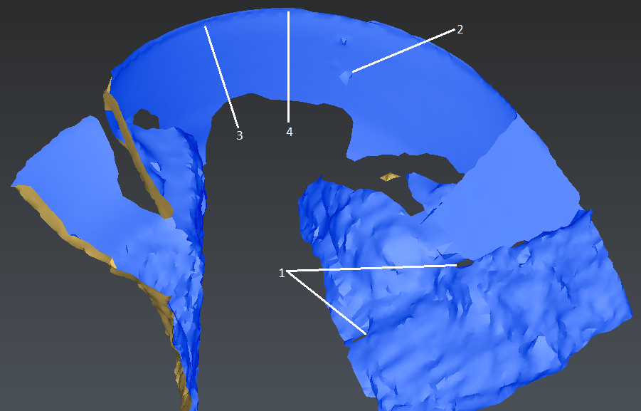 Figure 2: Making the first mesh with the default parameters to see what happens
You are now ready to analyze your first result. Here are the remarks that we can make after a brief sight:
Some areas where points are missing are completely filled by big triangles. These holes are about 2m wide. This would require to enter a value in the field Hole detection, triangle size below 2.
We get some aberrant points but the number of these points is really low. So an easy manual correction can be done afterwards.
The sharpness of the edges is not correct. This requires having smaller triangles.
The detail of the writings is not present in the mesh, however as these details are very small, we will include these details in a second step.
Making a regular mesh at a certain level of detail
The conclusion of the previous test is that the mesh should be done with a smaller triangle size:
Make undo.
Select again Cleaned Cloud.
Launch the command 3D Mesh.
Enter the value 0.3 for Average distance between points and 1.2 for Triangle size.
Click OK.
Type i or Reverse with the contextual menu to show the bright side on the front of the dam.
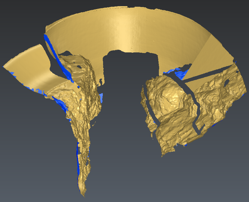 Figure 3: Meshing the dam with an average distance between points of 0.3m. The result is a mesh made of several disconnected parts: a compound mesh.
Explode the compound mesh and delete smallest parts
As you can see the resulting mesh is a “compound mesh”. This means that it is a group of several disconnected surfaces. We will now explode the compound into different independent meshes.
Select the mesh.
Launch the command Ungroup Mesh.
If you look at the object Explorer you should see that the mesh group contains many pieces. All these pieces are sorted by size: the biggest part is the first and the smallest is the last. We suggest keeping only the 4 firsts parts. Select from the 5th to the last mesh and delete all these small pieces.
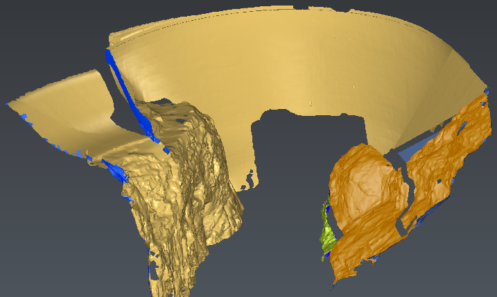 Figure 4: Explode the mesh into disconnected parts. You can select all the meshes and put them in the same color. It is easier to see on which mesh the normal color is reversed.
We can now group again the four biggest pieces inside the compound mesh.
Select all the meshes that you want to put in the compound.
Launch the command Group Mesh.
Say Yes to the orientation of the normal so that all parts will have the same normal orientation.
You can change the color of the new compound mesh. Select the mesh and choose a color in the contextual menu.
Filling some holes
We will now fill some holes. The automatic selection is often the fastest way to select the “smallest holes” to fill.
Select the mesh.
Launch the command Fill Holes.
Select the option Select borders shorter than (limit the free border length).
Set Length to 16 (do not put a bigger value; otherwise open contours will be selected).
Select the option Add points inside holes, Curvature filling and Prevent self intersection.
You can add or remove holes by clicking in the 3D scene.
Click Preview and OK, Exit.
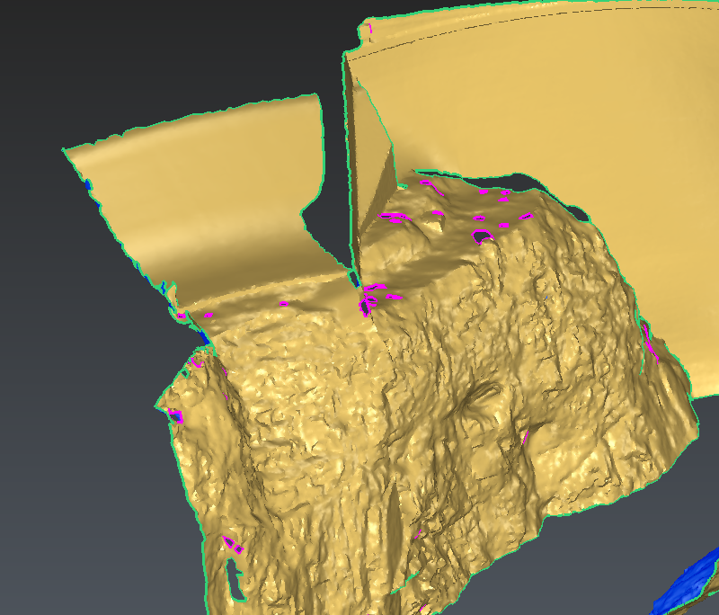 Figure 5: Automatic selection of the smallest holes to fill with curvature continuity.
Replacing some parts to remove some aberrant zones
At some points like on the image, you should see some defects on the surface. You can easily remove these aberrant zones.
Select the mesh.
Launch the command Replace A Part.
Draw a freehand contour to encircle the zone to correct.
If you are happy with this correction, click OK otherwise click Undo.
Do this operation for all the zones to be replaced.
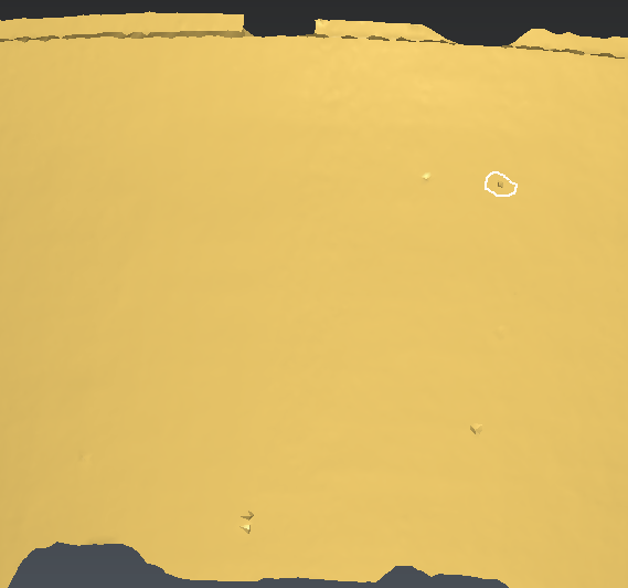 Figure 6: Aberrant zones can be easily replaced or locally smoothed.
Note that in some situation it is also possible to smooth the whole shape to get a better aspect but here we will not use this command because our intention is to keep the measurement points “as is”.
Making junction in between open contours
The model contains some zones that cannot directly be filled because they are open contours and not holes.
Launch Bridge and click on the two free edges to close the hole.
Activate Sew and OK, Exit.
Then, launch Fill Holes and click on the hole to fill it.
Make a junction between two contours
Launch Join 2 Contours and select the two contours.
Make restriction on the two contours as they are open. Wait for the computation to be done, then follow the instructions in the top of the dialog box.
Then, select Sew all the parts and click OK, Exit.
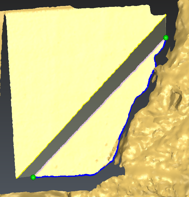 Figure 8: You can also create a mesh from two contours (polyline or hole border). A contour restriction is sometimes necessary.
Improving the accuracy of the mesh in specific zones
The model contains some sharp edge zones and we are going to improve the accuracy in these regions.
Select the mesh and all the clouds whose name starts by “SharpAngle” (press the CTRL key to select several elements).
Note that the clouds were previously split to prepare this tutorial.Launch the command Refine Mesh from Cloud.
Choose No noise reduction.
Set Deviation error to 0.03.
Check Distance and set 0.3.
Choose Extend free border and set Triangle size to 3.38478.
Click OK, Exit.
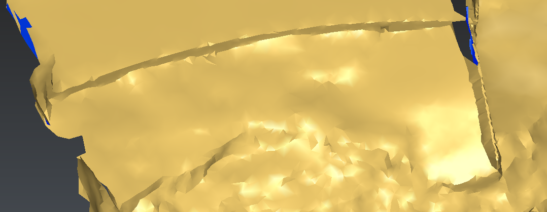 Figure 9: The "Refine Mesh" command improves the accuracy of the mesh
We can also improve the zone of the writings.
Select the mesh.
Press the CTRL key to add in your selection the cloud “writings”. Note that the cloud was previously split to prepare this tutorial.
Launch the command Refine Mesh From Cloud.
Choose No noise reduction.
Set Deviation error to 0.
Check Distance and set 0.3.
Choose Extend free border and set Triangle size to 0.53.
Click OK, Exit.
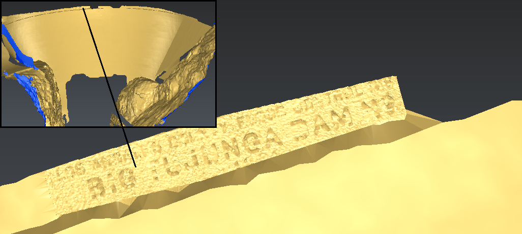 Figure 10: The Refine mesh command improves the accuracy of the mesh.
Note that a deviation error of 0 (zero) means adding all the points of the cloud. This could be dangerous for a big or noisy cloud.
Re-meshing locally the edges so that they look sharp and smooth
On the model, you should see 2 types of defects: the edges that are supposed to be sharp and smooth are jagged. And some spikes are present in the smooth regions. The smoothing command will improve these two defaults.
Select the mesh.
Launch the command Global Smoothing.
Choose Smooth noise.
Move the intensity slider to Low to apply only the reorganization.
Check Improve curvature areas.
And check Smooth Free Borders.
Press Preview, then OK, Exit.
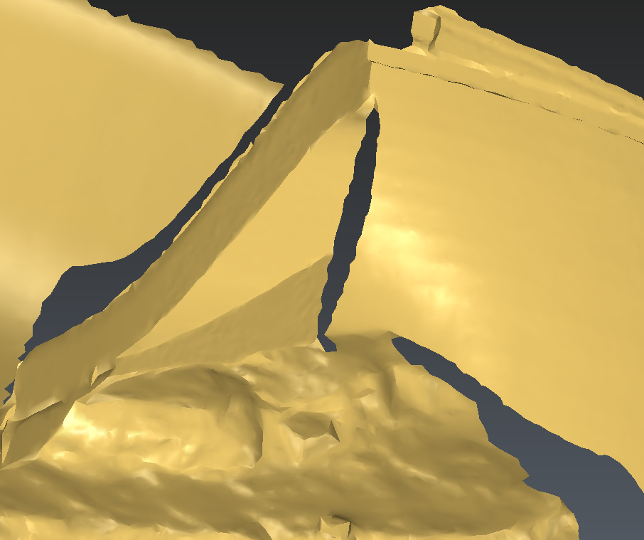 Figure 11: Using the smoothing command to make the edges sharper and to correct spiky regions.
Note that by default, the intensity slider is in the middle to globally smooth the entire model. A global smoothing is not the most appropriate choice in this case because only a part of the model is smooth (the dam structure).
Extracting some features from the model: planes, cylinders
From this model, you can very easily extract some features like planes and cylinders.
Select the mesh.
Launch the command Region Grow Cylinder.
Click 2 or 3 points.
In this case you will need to help the extraction indicating that the cylinder axis is fixed to Z axis.
You can slide the extraction tolerance to change the tolerance of your feature.
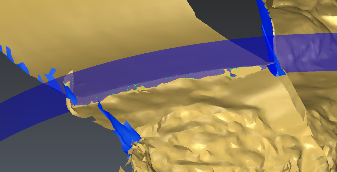 Figure 12: The Region Grow command allows you to create planes and cylinders among other geometrical shapes, fitting on your model.
Plane, cylinder and sphere extractions require one or few points.
Once your cylinder is created, you can check the label output to create a label. You can edit it with Edit Label, a dialog box allows you to enter some information like the reference value, the tolerance. You can also disable some values that are not relevant for your inspection.
The position of the label is automatically calculated by the software.
Creating a freehand section
We will now create a section just below the top of the dam.
Select your model.
Launch the command Free Hand Section.
Choose the option Best plane and click 3 points on the model as shown on figure.
Click OK, Exit to validate the result.
Launch the command Cut Polyline.
Click points on the polyline on the dam extremities.
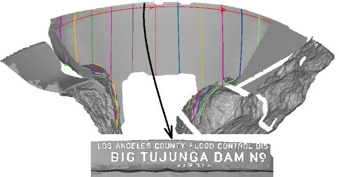
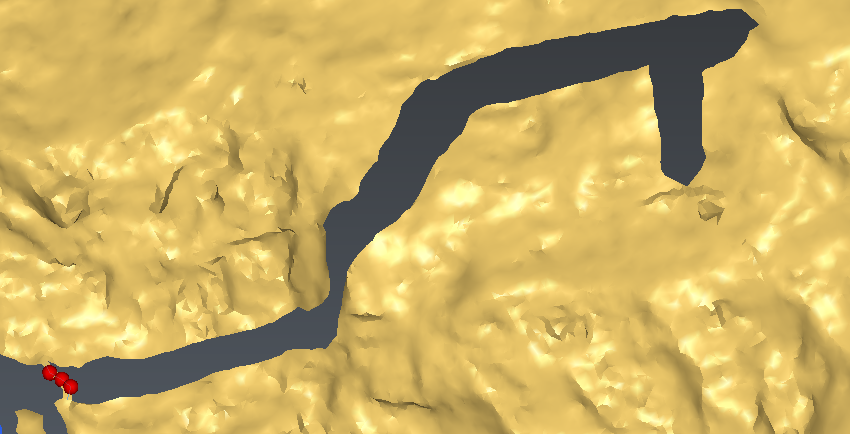
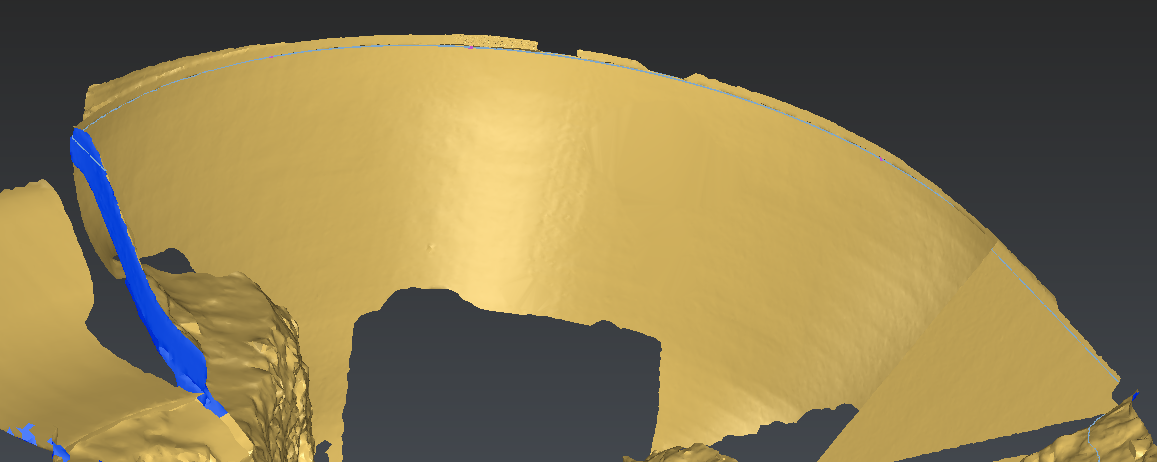 Figure 13: With the command Freehand sections you can make a planar section on the fly.
The main part of the section will become the reference line to create sections. You can delete all the other parts.
Creating some sections along a curve
We will now create some sections along the path that we have created.
Select both your model and the polyline.
Launch the command Sections along Curve.
Choose Regular.
Set Step to 10, choose All over for the range.
Check Searching Distance and set the value to 50.
Click Preview and OK to validate the result.
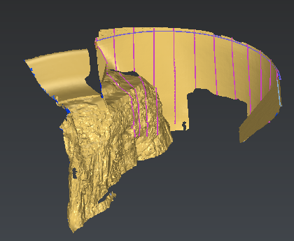 Figure 14: Using the command Sections along curve to make planar sections perpendicular to a path.
These sections can be used for different purposes:
Export for CAD software using the DXF or IGES format.
Split the mesh in several parts with the command Mesh \ Constraint Meshing.
Reconstruct a CAD model inside the software. Note that the CAD reconstruction requires the AEC license.