Object representations
Different representation modes are available for the different objects inside the software. Some of these representation modes are always available and some are available only if the component contains the necessary information. A typical example is the Inspection representation which is only available for a cloud (or mesh) only if the cloud (or mesh) has been inspected (or if an intensity value is associated with each point)!
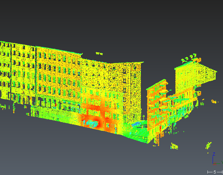
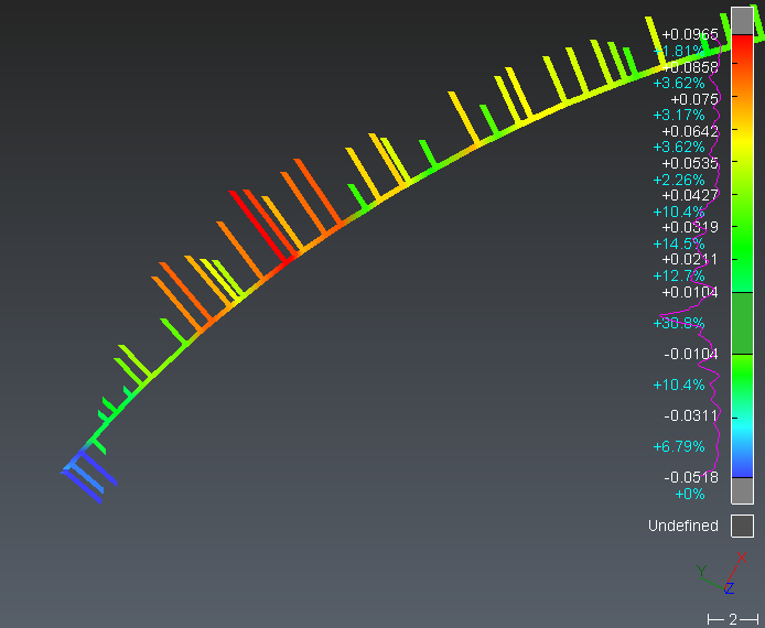
Note about inspection representation mode
In this mode, the colors associated with the points are defined according to a gradient which can be edited by the user with the Edit Colors command.
For some objects, it is important to understand the concept of the normal orientation to understand the representation. The normal of an object is the "outside" of this object. The “outside" is the side from where the object is scanned/viewed. At the opposite, the "inside" means inside the material itself. For instance, the orientation of meshes or surfaces is very important for inspection. In the software, meshes and surfaces have a color for the “inside” and another one for the “outside”, so it is very easy to detect when the normal is not correctly oriented. The “outside” color is also shinier than the “inside” color.
To change the transparency, select your object, then do a right click and select Transparency (not available on polylines), or use the representation icon in the tree.
More parameters are available in the command Settings. This command allows you to change more displayed parameters for each type of objects (clouds, meshes, polylines …). You can change default parameters (for all objects you will create or import), or current parameters (for the selected objects).
List and preview of representation:
|
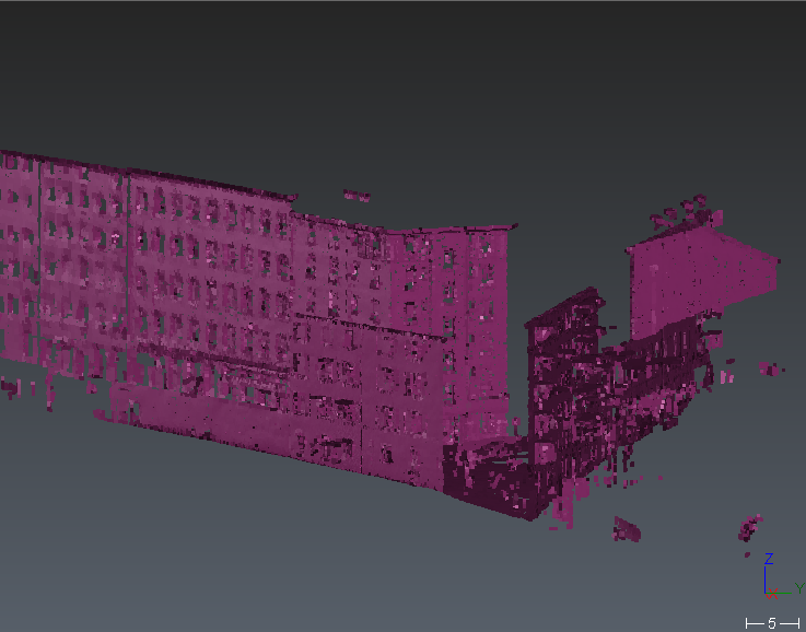
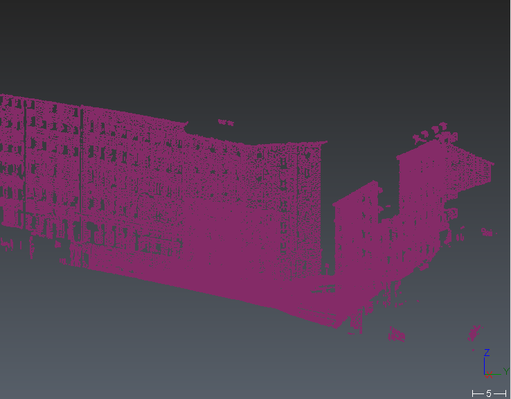
CLOUD |
||
|
Smooth |
Always available |
|
|
Flat |
Always available |
|
|
Smooth with back in reversed color |
Available if scanning position/directions are known |
|
|
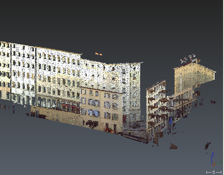
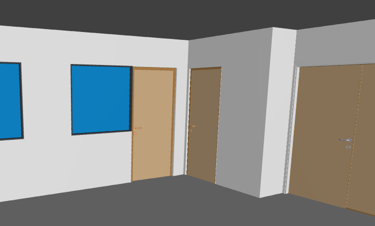
Real Color |
Available if RGB colors are known |
|
|
Inspection |
Available with intensity or inspection value. |
|
|
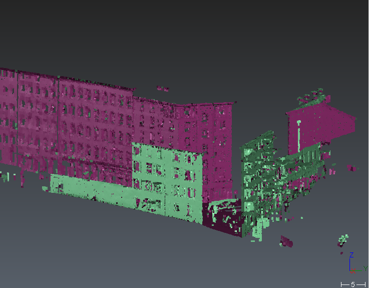
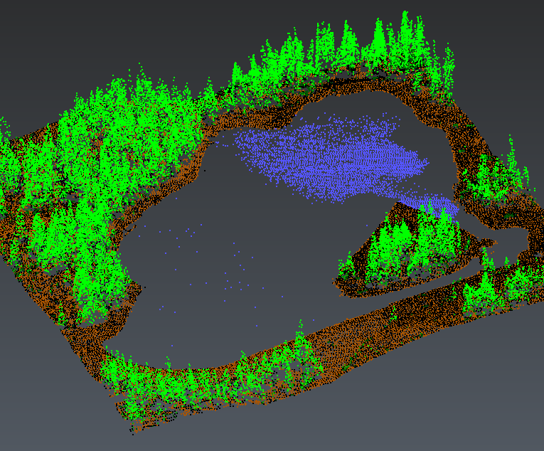
Classification |
Available if classified points |
|
|
MESH |
||
|
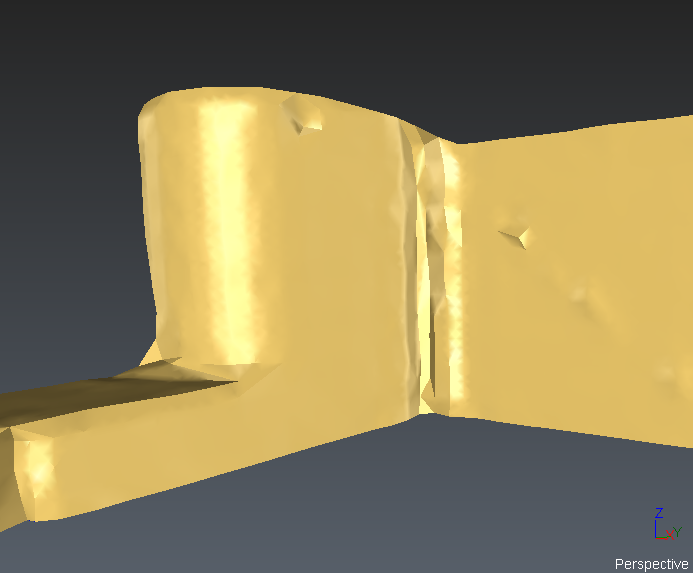
Smooth |
Always available |
|
|
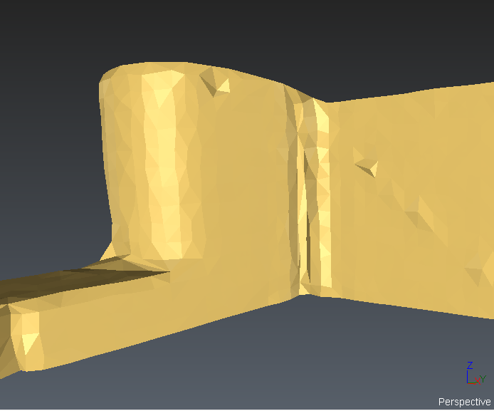
Flat |
Always available |
|
|
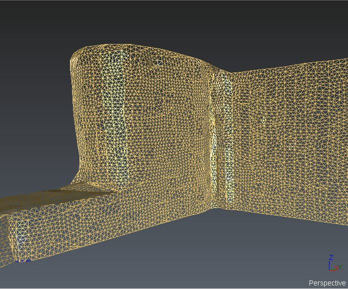
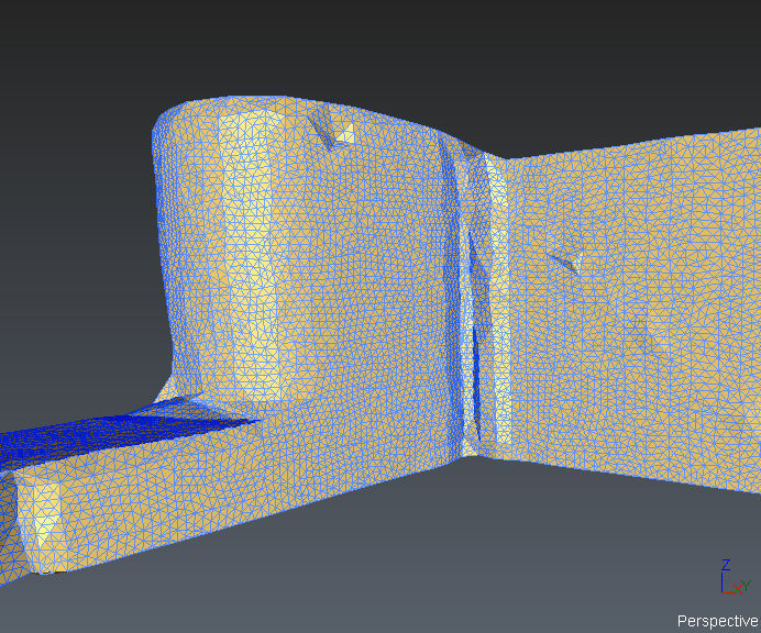
Wire |
Always available |
|
|
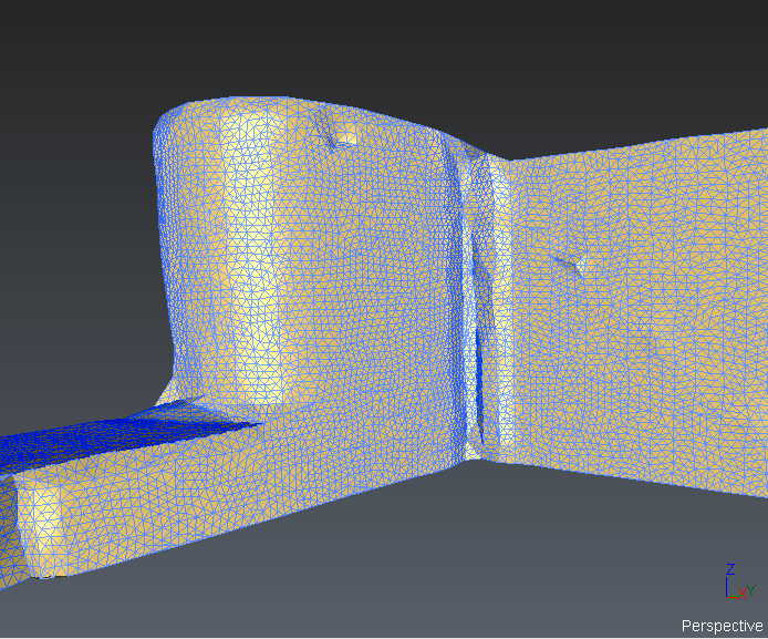
Smooth + Wire |
Always available |
|
|
Flat + Wire |
Always available |
|
|
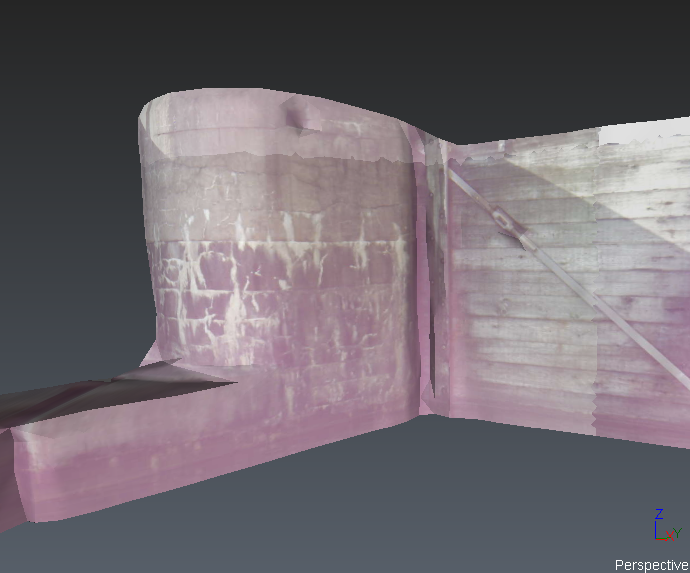
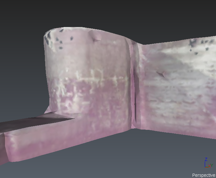
Textured |
Available if texture is defined (images applied to the triangles) |
|
|
Real Color |
Available if a RGB value (color) is associated with the vertices |
|
|
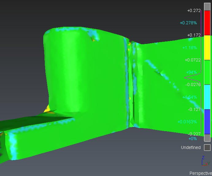
Inspection |
Available if an intensity or an inspection value is associated with the vertices |
|
|
Color per triangle |
Only available when the mesh comes from a BIM object. The color is associated with the triangles. |
|
|
POLYLINE/SET OF POLYLINES |
||
|
Segments |
Always available |
|
|
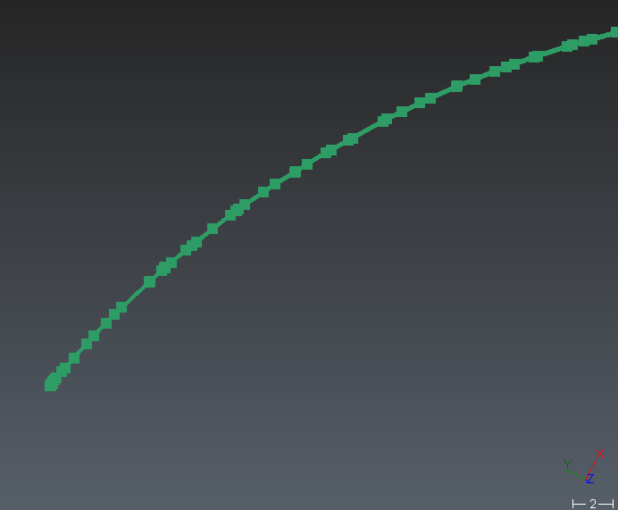
Segments and vertices |
Always available |
|
|
Inspection |
Available if an inspection value is associated with the point |
|

You can also display the names of points, polylines, set of polylines in the scene by checking the option 'Show Text'.
|
CAD SURFACES |
||
|
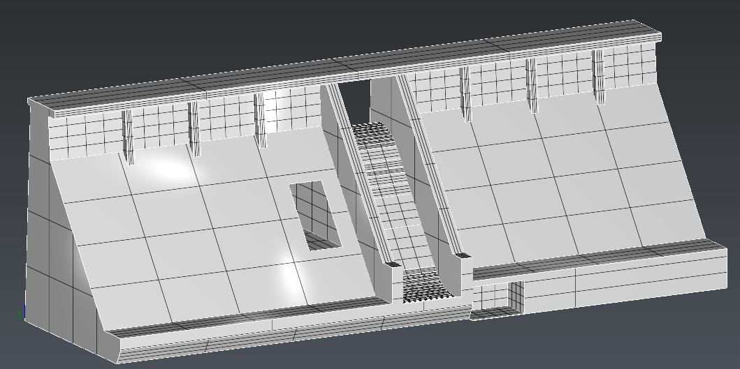
Smooth + Isometrics |
Always available Isometrics can be hidden. |
|
CAD Representation
Sometimes, you may see that some CAD objects or polylines converted from CAD curves (AutoCAD) do not have a good aspect (not smooth enough, too much segmented). This is a side effect due to the technique used to represent a NURBS surface.
A NURBS surface cannot be displayed “as is”. It requires some transformation so that your graphic board can make the representation. This transformation is called “discretization” and consists in sampling the continuous surface or curve with “discrete” points.
In this process, the surface or curve is “simplified” with a certain error called “deflection”. By default, the software takes an adaptative deflection based on the dimension and the scale of the objects; but in some cases this value is not low enough to get a good representation. In such situation, it is possible to set the discretization independently thanks to Edit display discretization command which can be run on each object (directly from the treeview).
|
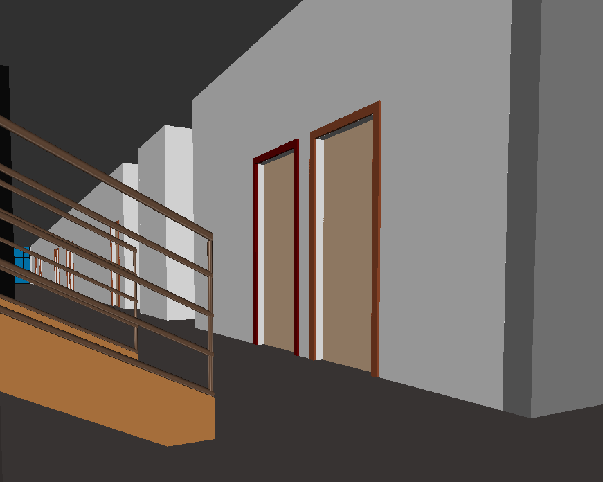
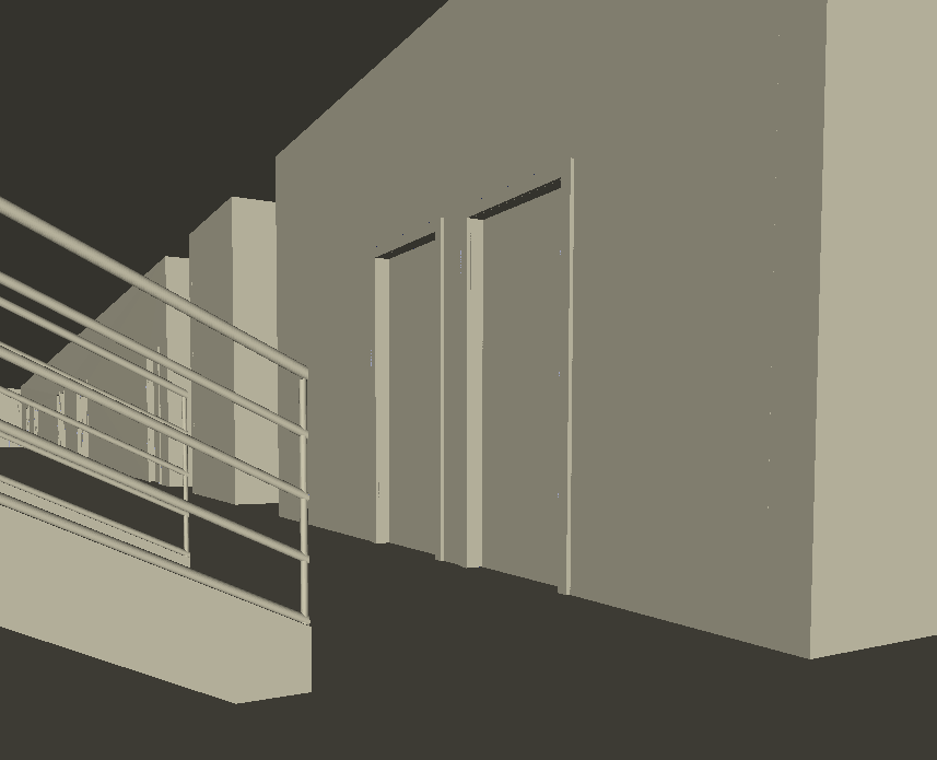
BIM Object |
||
|
BIM |
Colors and transparency stored in .ifc or .rvt. Always available |
|
|
Flat |
Single editable color. Always available |
|