Exercise: create an ortho-image and import it in AutoCAD
Create the ortho-image
Open the file FrontageOrthoImage.3dr.
Launch the command Extract OrthoImage and select Elevation view for the OrthoImage mode.
Give the 3 points as described in the picture below to define the frontage to map (ensure XYZ mode is enabled in the toolbar). The 3 points can be clicked accurately in orbit orthographic camera mode or given by coordinates.
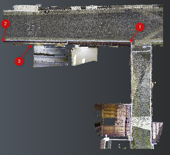 Frontage to map
Now, you can adjust the defined box to capture exactly what you need. This is possible either through the scene by editing the limit box (in 3D frame view) or though the dialog box by editing the size, the depth, and the top left corner. To keep horizontal lines, horizontal in the orthoimage, it is advised not to modify Horizontal parameter.
You can activate the Preview to visualize the changes in real time.
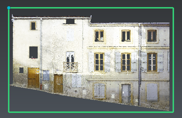 Image preview
Set the image properties parameters as below:
Pixel size: 0.01 m,
Point/Line magnification: 1,
Background color: white.
Then Save image as a picture file. In the dialog Select the destination file..., enter orthoimage as file name and choose jpeg as file format.
Two files have been created:
orthoimage.jpg: the picture
orthoimage.txt: the georeferencing file
Insert the image in AutoCAD
Warning
Choose counterclockwise either Decimal Degrees or Radians and Meters as Drawing Units (enter UNITS in the command line prompt or launch Units from the menu Format).
Open orthoimage.txt with a text editor like Notepad and an empty file with AutoCAD.
From AutoCAD, enter IMAGEATTACH in the command line prompt and select orthoimage.jpg
Tip & Trick
You can also add a Raster Image Reference... from the menu Insert... or from the ribbon.
Uncheck all the options as below.
Then copy-paste the insertion point from orthoimage.txt (see the Autocad import section) to Insertion point group.
Do the same for the Scale and set the Rotation to 0.
Validate with OK.
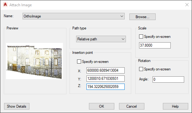 Attach Image
Rotate the image in AutoCAD
Now, it is necessary to rotate the image.
Warning
If more than 1 rotation is needed, remember that a first rotation along an axis will modify the 2 others axis.
If rotation Z is not 0,
enter ROTATE3D in the command line,
select the image,
select the Z axis direction,
select bottom left corner in image object and copy-paste rotation Z.
Then if rotation X is not 0,
enter ROTATE3D in the command line,
select the image,
use the bottom left and bottom right points of the image object to define the rotation axis (X'axis)
copy-paste rotation X.
Finally, if rotation Y is not 0,
enter ROTATE3D in the command line,
select the image,
use the bottom left and top left points of the image object to define the rotation axis (Y"axis)
copy-paste rotation Y.
Command: ROTATE3DCurrent positive angle: ANGDIR=counterclockwise ANGBASE=0Select objects: 1 foundSpecify first point on axis or define axis by[Object/Last/View/Xaxis/Yaxis/Zaxis/2points]: zSpecify a point on the Z axis <0,0,0>:Specify rotation angle or [Reference]: 179.2574996998036Command: ROTATE3DCurrent positive angle: ANGDIR=counterclockwise ANGBASE=0Select objects: 1 foundSpecify first point on axis or define axis by[Object/Last/View/Xaxis/Yaxis/Zaxis/2points]: Specify second point on axis:Specify rotation angle or [Reference]: 90Now the OrthoImage is inserted in 3d in Autocad scene.