Planar Sections
![]()
This command computes sections or set of sections of selected mesh(es) or cloud(s), computing the intersection between parallel planes and select object(s).
Requirements
Select all the mesh(es) or cloud(s) on which you want to calculate sections and launch the command.
For meshes:
Enter the direction of the axis.
Extraction method: choose where the sections are calculated:
Regular: with a regular step, for example, one section each 10m.
All over: all over the object. Check Pass Through to force the section to pass through a given point.
Custom: only between two points
List of values: pick points or enter values to choose where to calculate sections.
Check Chain opened sections option to chain the section. The "chaining" is an operation which connects all the opened polylines on one cut plane.
Check Offset option to make an Offset of the link connecting different polyline pieces. Chaining sections is very interesting for laser cutting tool paths were you need continuous polylines. Offset can be useful to keep track of the holes or undefined zones in the model.
For point clouds, there are further options:
Enter the Slice thickness in which the points of the cloud will be taken into account when computing the sections.
Set the Chaining distance in order to set the connection between opened polylines.
Activate or not the Noise reduction to keep only the best points of a section.
For meshes with inspection data, you have the option to create section with inspection data.
Create inspected section: select to create a section with inspection data
Magnify: Scale the pegs length
Technical information
Sections on an inspected mesh
If the sections are computed on the inspected mesh (considered as well as the reference or measure), the sections will keep the inspection values of the mesh. It means that the hair diagram will not be, in most cases, in the plane of the section. It depends on the type of inspection (2D or 3D).
Restriction: when a mesh was colored as the measure with a cloud as reference, this capability is not available.
Example of a hair diagram in 3D on a planar section:
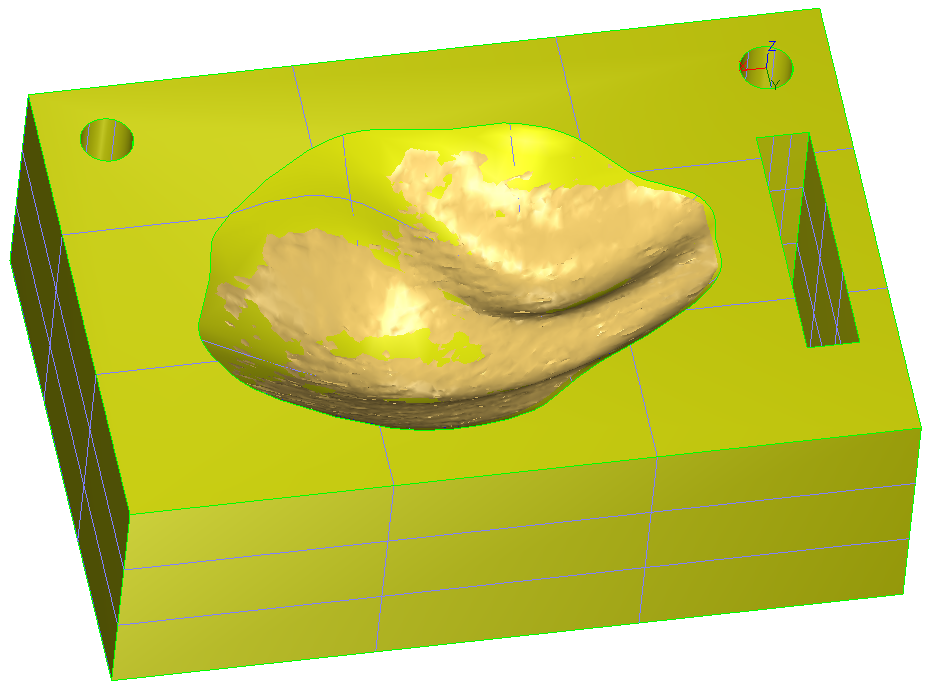 1. CAD and mesh used to compute the inspection
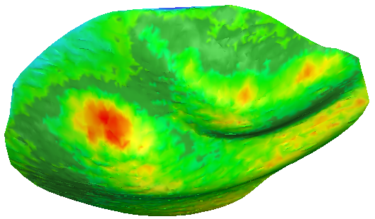 2. 3D Inspection with colors applied on the 3D mesh
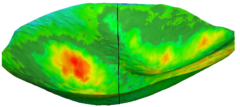 3. Section on the inspection mesh (Y plane)
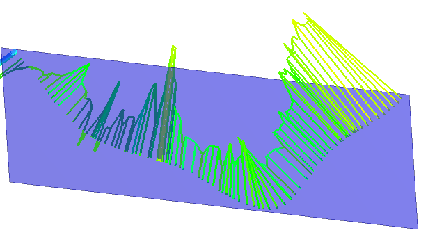 4. Plane Y and hair diagram in 3D: direction of the deviation
If you want to have a hair diagram on the plane of the section:
Do an inspection in the direction of the plane and then do a section with this plane.
Do a section in the plane on both entities (reference and measure) and then do an inspection of this polyline/set of polylines.