vs Section
The Section here is the reference object for the inspection.
Case of polylines and/or linear features
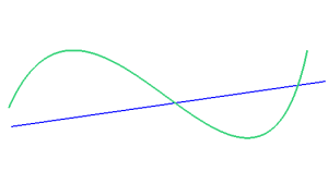
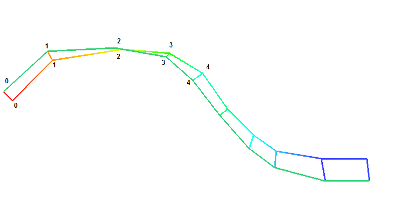
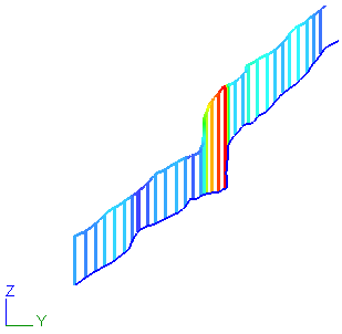
The result of an inspection between 2 polylines, or between a linear feature and a polyline, gives you an inspected polyline with a "hair diagram". This diagram represents the deviation between the reference and the measure. As for all other objects, both reference and measure can be colored. But, in all cases, the hair diagram starts from the reference and goes in the direction of the measure. This deviation can be magnified by a dedicated slider in the command Edit Colors. It means that the deviation is always exaggerated in the direction of the error (reference to measure).
|
Inspection polyline/polyline or linear feature/polyline |
Color the reference |
Color the measure |
|
Blue: reference Green: measure |
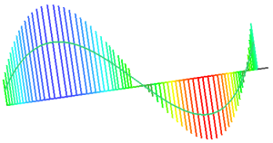
The color gradient is applied to a copy of the reference with a magnified hair diagram. The measure keeps its color (green). |
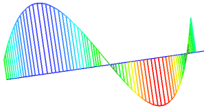
The reference keeps its color (blue). The color gradient is applied to a copy of the measure. In this case (measure is colored), both hair diagram and copy of the measure are amplified. |
Point to point inspection
In case of having 2 polylines with the same number of points, 2 options are possible:
Use projection to compare is actually the 3D projection (points of the measure will be projected on the reference).
Point to point means that the magnitude of the inspection is the distance point to point, for every couple of points (one on the reference, and one for the corresponding point on the measure). If the polylines are not oriented in the same direction, the measure is reversed to be oriented in the direction of the reference.
|
Inspection between 2 polylines |
Use projection to compare |
Point to Point (need polyline with the same number of points) |
|
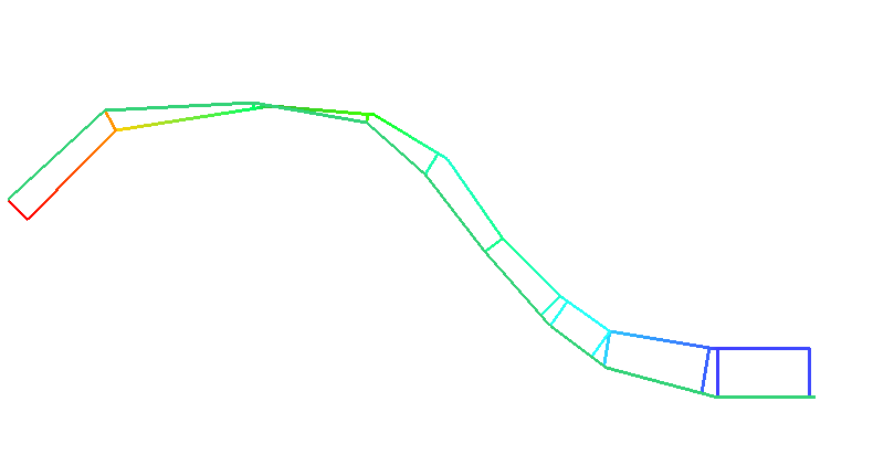
Reference: black polyline Measure: green polyline For the two examples on the right, we decided to color the reference. |
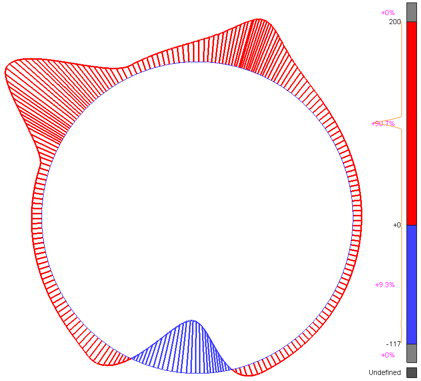
In this case, each vertex of the measure is projected on the reference. Then, we take each vertex of the reference - if it doesn't already have a computed inspection value -, and we look for the point on the measure which projects itself on the reference. The vertex's inspection value corresponds to the distance between this point and its projection. The inspection between 2 consecutive vertex is linear. It may happen that 2 vertex of the measure have the same projection on the reference. In this case, 2 lines go to the same point. The display of the lines is also relative to the zoom factor and the angle between lines. |
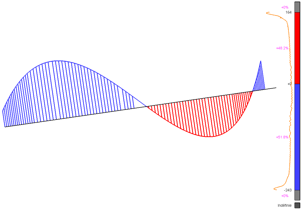
In this case, we just take pairs of points (the vertex 0 of the measure, and the vertex 0 of the reference, and so on). We compute the 3D distance of each pairs. The vertex's inspection value corresponds to the distance between those two points. The inspection between 2 consecutive vertex is linear. |

Sign of the inspection
In case of having 2 planar elements, no mandatorily coplanar, but in parallel planes, it is possible to give a sign or not to the inspection using the option Unsigned inspection. In this case the sign means which part is above/below or inside/outside the reference, in the view of the normal of the planes.
Note: using a geometrical shape as a reference (circle...)
When using a geometrical shape as a reference, the measured polyline does not need to be planar. Only the direction of the plane of the reference will be used to give the sign.
Direction of the inspection
In case of having 2 coplanar elements, it is possible to compute the inspection in a given direction. In this case, inspection can also be signed or not according to the direction vector.
|
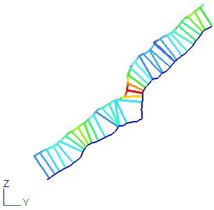
3D inspection |
2D inspection in Z direction |
|
|
|
2D Inspection
The given vector used to define the direction of the 2D inspection must be in the same plan than the plan defined by the 2 coplanar elements.