Exercise: Modeling pipe traces
In this exercise, you will create a model of pipe traces.
Open the file PipeTraces.3dr.
Understand what can be edited after extractions
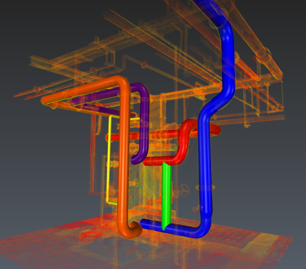
In this file, a scan to pipe project has already been performed to draw 6 traces. Click the play icon next to the folder called Scan to Pipe. You can see a list showing the traces that you can delete, show/hide or modify their colors.
Note you can also adjust the cloud and pipes transparency.
In the 3D scene, hover over and click on any straight element of the purple trace; then delete the pipe element. The trace will be split. You can recreate the missing straight pipe by simply connecting the pipes that form its ends: select one extremity + Connect with straight pipe in the toolbar and then select the other corresponding extremity.
Now select a straight element in the red trace. Edit its diameter using the dialog (for instance 0.25m): the diameter will be propagated until next reducers. Caution: the elbows geometry in the trace may restrict the diameter (for instance, try 1m). In the same way, if you move the arrows, the adjacent elements will be modified. Globally, extend or shorten the straight elements is not necessary unless the element is located at the end of the trace.
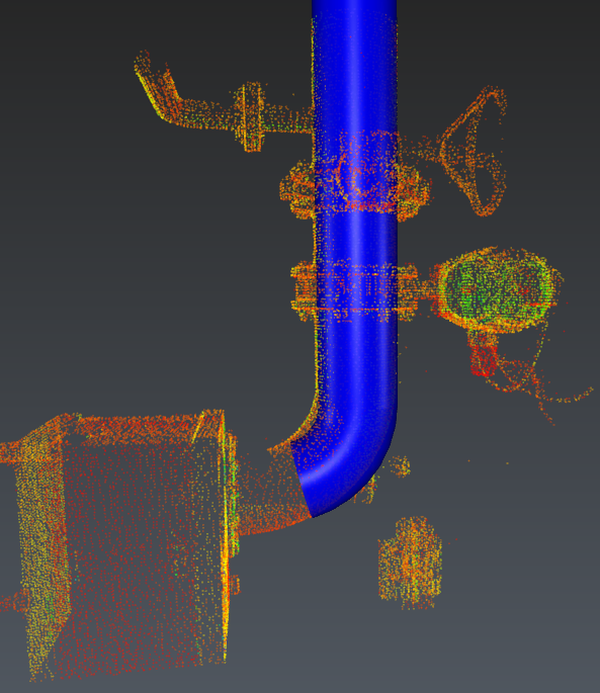
Select an elbow in the middle of the purple trace. You can edit the diameter like you did with the straight element. You can also modify the bend radius (either through the dialog box or the 3D scene): this is necessary to fit the elbow exactly on the cloud. The angle can only be modified when the elbow is an extremity. Click the elbow at the bottom of the purple trace: set the angle to 90°. This is very useful for traces ending with an elbow or when a trace deviates from the cloud (due to a lack of points for the extraction algorithm). In such case, delete the bad elements, adjust the elbow angle and continue the trace from this elbow using a straight element.
Finally, select a reducer at the bottom of the blue trace. You can edit the diameter like you did for straight and elbow elements. Note that a reducer can manage alignment offset. This setting is only available at the trace extremities.
To conclude: keep in mind that the properties of the first selected element will be propagated. You should always start the propagation with the most reliable elements, especially considering their direction.
 Exercise preview
Extraction
Exit the current workflow and hide it. Then, select the cloud and launch Scan To Pipe.
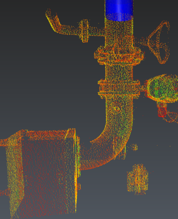
Start the new pipe trace and try to create again the purple one. Since the direction of the extracted element will be propagated it is very important to begin with the most confident area (not noisy, free of other objects and long enough). This is not necessary to begin with an extremity because both ends can be extended at any time.
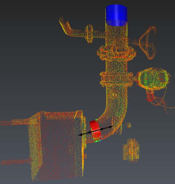
Give 2 seed points, the algorithm creates a straight element between them. Arrows are displayed to extend/shorten the element (use TAB to give numeric values). However, this is only necessary in two cases: where it corresponds to a reducer or a trace end. Press ENTER to validate the element.
Then, continue the trace by adding an elbow+straight and giving another 2 seed points. Adjust the bend radius using the arrows. Note that the end to be extended will be found automatically. If you exit the trace creation, simply select an extremity element and continue the pipe trace.
The fitting elements (reducer or elbow) must be separated by a straight one and their orientations only depend on the directions of the adjacent elements. To finish the purple trace by an elbow with a very short straight, you can proceed as following:
 Stop the current trace creation
 Create a new pipe trace: extract a temporary straight element (the accuracy doesn't matter)
 Connect both straight elements beginning by the most confident one (the top one)
 Remove the straight at the bottom
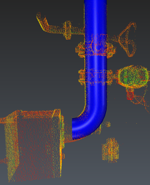 Modify the elbow (angle and bend radius)
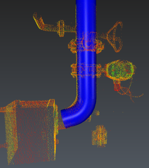
 Continue the trace by a straight element
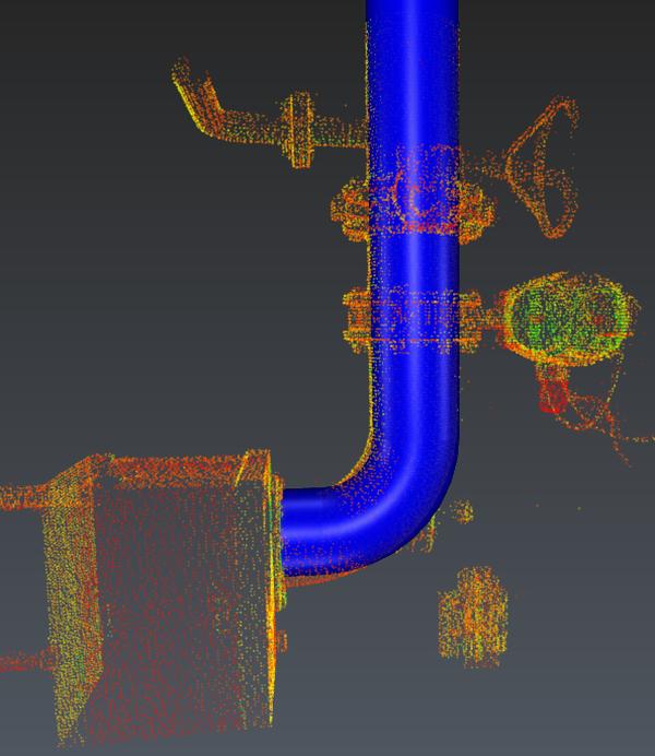
This method is also suitable to manage complex sequences you will face in red and blue traces. Moreover, it is possible to give extraction constraints before giving the seed points.
When all traces are drawn, go to the next workflow step.
Export
For BIM export, you can rename pipe elements and give them a thickness using the list (double click on the default thickness). Otherwise, select directly the appropriate export among:
Mesh: pipes traces will be exported with discretized surfaces (like they are displayed). Optionally, send directly the traces to another application: refer to Send to.
CAD: pipe traces will be exported using geometrical CAD shapes.
Center axis: only the center axes and the ports will be exported.