This command allows to modify a polyline manually.
Requirements
Select one polyline and launch the command. You also can double click on a polyline or launch this command through the treeview if the current polyline representation mode is not inspection (otherwise, it will launch Edit Colors).
|

|
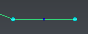
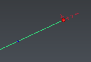
Red balls will be displayed on vertices.
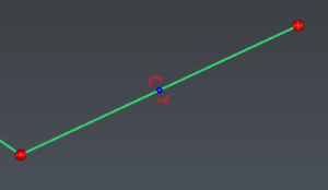
Small blue balls will be displayed on segments.
These balls are displayed according to the current zoom factor.
|
|

|
Select vertices:
You can:
|
|


|
Keep the mouse on a ball to display options, then choose one:
 : add new segments:
DEL: undo the last created segment,
ESC: cancel the new segments and exit the option,
ENTER: validate the new segments and exit the option.
 : add new perpendicular segments. Select the current mode with SPACE:
Free mode: give a point to define each segment length.
DEL: undo the last created segment,
ESC: cancel the new segments and exit the option,
ENTER: validate the new segments and exit the option.
Junction mode:
add a new perpendicular segment, extend it to another polyline, then merge both polylines.
Hover the polyline to join, to visualize possible combinations in magenta.
Intersection mode: add a new perpendicular segment and extend it to another clicked polyline. Both polylines will not be merged.
 : extend or shorten the segment. Select the current mode with SPACE:
Free mode: give a point to define the new segment length.
Junction mode:
extend the segment to another polyline
,
then merge both polylines.
Hover the polyline to join, to visualize possible combinations in magenta.
Intersection mode: extend the segment to another polyline. Both polylines will not be merged. Hover the other polyline to visualize the result in magenta.
 : add or insert a discretized arc.
blue ball to insert a discretized arc: give an intermediary point and define the maximal deviation allowed.
red ball to extend with a discretized arc:
3 points arc: give an intermediary point and the extremity, then define the maximal deviation allowed.
tangent arc: give the extremity and define the maximal deviation allowed. The created arc will be tangent to the previous segment.
-
Maximal deviation allowed
 : insert a new vertex.
Repeat with another option.
|
|
|
Press
ESC to invalidate the whole edition session
or ENTER to validate and exit the edition command.
|
Notes
New vertices will be added in the current polyline best plane, unless all current vertices are aligned (screen direction will be used instead).


