Extract pipes
![]()
This step extracts pipe traces from a point cloud. A pipe trace is made of a succession of contiguous pipe elements. 5 types of piping elements are available:
Elbow: defined as a portion of a torus.
It is characterized by the radius of the underlying torus (called Bend radius), the Diameter of the pipe and the deviation Angle of the elbow.
Constraints: the Angle must lie within the interval ]0°; 180°]. The Bend radius must be strictly greater than the pipe radius.
Reducer: defined as a junction between 2 parallel circular sections. The sections are not necessarily coaxial (we say that the reducer is eccentric - the amplitude is quantified by the Offset).
Straight pipe: defined as a cylindrical section with a given Diameter.
Y or T branch: defined as a junction between 2 or 3 elements. The main Diameter concerns the pipe run and the Second diameter is the diameter of the outlet.
Flange: defined as two rings, possibly separated by a gasket.
Hide / show the input cloud, extracted points or pipes using the bulbs. Adjust their transparency using the sliders.
You may also
 Filter the cloud according to its classes: see Auto Classification.
All previously extracted traces are displayed in the Extracted pipes tree:
You can duplicate, zoom on, delete, change color and show / hide each one.
Unfold a trace: y ou can zoom on and delete each element.
A toolbar is displayed in the scene to provide extraction and connection tools for pipe elements:
Use
 Start new trace to initiate a new pipe trace. Begin either by extracting a
  straight pipe or using auto extraction from the point cloud.
 Auto extraction allows to extract multiple elements of a trace automatically. Click a point on the cloud of a well-defined straight pipe to extract it: the tool will try to extract the whole pipe trace by propagating the extraction all the way. If it doesn't extract everything, click on the next straight pipe: the extraction will resume. To help the extraction, you may add some constraints, which may be enabled and disabled between each click to better suit your cloud:
Diameter: the diameter of the current extraction
Use standard angles.
Symmetric reducer.
Semi-auto extraction
 Elbow + Straight pipe extracts a straight pipe from selected points. Then, the extracted straight pipe will be connected with an elbow to the previous element (the elbow is automatically fitted on the cloud). This extraction will therefore be constrained accordingly:
The elbow and its two straight pipes will have their center-lines co-planar.
The diameter of the previous element will be propagated.
Note that the Angle of the elbow can be locked to a specified value or can be forced to a Standard angle.

 Reducer + Straight pipe extracts a straight pipe from selected points. Then, the extracted straight pipe will be connected with a reducer to the previous element (the reducer is automatically fitted on the cloud). This extraction will therefore be constrained accordingly:
The axis of the extracted pipe will be collinear with the axis of the previous element.
Both reducer diameters will be set according to the adjacent pipes.
Note that the Diameter 2 can be locked to constrain the extraction of the straight pipe.
Note that it is also possible to constrain the extraction to a symmetric reducer (both straight pipes and the reducer will be coaxial).
-
Straight pipe extracts a straight pipe from selected points. Then, the straight pipe will be connected to the previous element. The extraction will therefore be constrained accordingly:
The axis of the extracted pipe will be tangent to the axis of the previous element.
The diameter of the previous element will be propagated.
If it is the first element of a pipe trace, the Diameter can be locked to a specified value.
If the previous element is also a straight pipe, both straight pipes will be merged.
 Flange extracts a flange from selected point. The extraction will be constrained accordingly:
A flange can only be extracted on a straight pipe.
Since the extraction relies on the straight pipe, the more accurate the straight pipe was extracted, the better the flange will be inserted.
 Edit pipe to enter pipe edition mode.
-
Start new trace validates the current pipe trace and starts a new pipe extraction.
 Validate trace and exit validates the current pipe trace and exits the extraction mode.
 Continue trace launches the main extraction toolbar while taking into account what has already been extracted. The extracted element will be automatically connected to the selected trace. Select any trace or element to make it enabled.
 Connect traces toolbar allows to join two distinct traces with the corresponding element:
Select an element of the pipe trace to connect, then click Connect traces to enter the Connection toolbar. Choose the desired type of connection. All available extremities for a connection will be highlighted with a black circle. Finally select the desired extremity of the pipe trace to connect. In order to guarantee the integrity of the resulting pipe trace, the diameter of the second pipe trace selected may be resized / realigned to propagate the connectivity constraints of the successive pipe elements.
 Connect with elbow: a user-defined Angle or a Standard Angle may be forced.
-
Connect with reducer: a Symmetric reducer may be forced.
 Connect with straight pipe.
 Connect with Y or T branch: a user-defined Angle or a Standard Angle may be forced.
Creating a connection through a Y/T branch is slightly different: select first the main direction thanks to a straight element (or an extremity element) then click 1 or 2 other elements. The Y/T branch will be inserted and adjacent elements will be adjusted (with new straight elements if necessary).
 It is possible to Duplicate the entire pipe trace.
 Delete: deletes the selected pipe element.
If a pipe element is selected in the scene:
The pipe trace containing the element will be automatically selected and expanded in the Extracted pipes tree.
Visual gizmos will be displayed in order to edit the element:
For reducers, straight pipes and Y/T branches: the black arrows are used to manage the length of the element along its axis. Use TAB to enter numeric values.
For elbows: the arrow is used to edit the bend radius and consequently both adjacent straight pipes length at the same time.
For flanges: the arrows are used to manage the length of the element along its axis, symmetrically from its center. If not at the end of the trace, the grey sphere allows to move it along the underlying straight pipe.
Specific parameters will be displayed in the command:
For straight pipes: the diameter can be edited.
For reducers: the diameter and the second diameter can be edited. The offset can be edited only if the reducer has exactly one free extremity.
For elbows: the diameter and the bend radius can be edited. The angle can be edited only if the elbow has exactly one free extremity.
For Y or T branches: the diameter and the second diameter can be edited. The angle can be edited only if the Y/T has no element on its secondary direction.
If edited, the diameter will be propagated until the next reducer.
Since the bend radius of an elbow has to be larger than the pipe radius, the propagation may stop and an error message will be displayed.
Since the second diameter of a Y/T has to be smaller than its main diameter, the edition of trace diameter connected to a branch can be limited.
Notes
Standard angles consist of this list: 5, 15, 22.5, 30, 45, 60, 90, 120, 135, 150, 157.5, 165, 175 and 180°.
The propagation of constraints can fail when the geometry of the pipe trace is not compatible with the new constraints. In this situation, only the elements which could have been changed are modified. A break in the continuity of the trace will be observed at the point where the constraint cannot be satisfied (not necessarily at the connection point).
Any edition of the current trace will trigger a whole realignment to the cloud to ensure the best overall extraction. This realignment will be carried out in such a way as to maintain the fit of the extracted elements with the extracted points of each straight pipe.
Use Undo button to cancel the last edition and Redo button to re-enable it. At any time, you can go back up to 30 steps. Older history will be permanently lost. Changing visibility of the cloud or pipes doesn't count as a step.
A warning sign may appear after an extraction or fitting: it means one or several element may be unviable. Unfold the trace to see which elements are concerned. Hover over it to see what property to correct.
Keyboard shortcuts:
Start new pipe trace
+
Continue pipe trace
C
Auto extraction
0
Continue with elbow + straight pipe
Connect with elbow
1
Continue with reducer + straight pipe
Connect with reducer
2
Continue with reducer + straight pipe
Connect with reducer
3
Connect with branch
4
Create Flange
5
Duplicate pipe trace
D
Edit pipe
E
Delete
DEL
Validate pipe trace
END
Technical information
Semi-auto extraction:
Straight pipes are extracted from the point cloud according to 2 seed points (reducers and elbows are using the point cloud automatically using adjacent straight elements). These two points have to define a reliable extraction zone since the algorithm only considers the part of the cloud between these two points.
Click on areas standing for the same straight pipe without noise and free from other elements. As much as possible, try to give two points which are opposite according to the pipe section.
The two points should be as far from each other as possible along the pipe to better detect its direction.
Note that the pipe elements will be extended automatically while continuing the trace extraction and performing connections: at this step, don't focus on the completeness of the pipe.
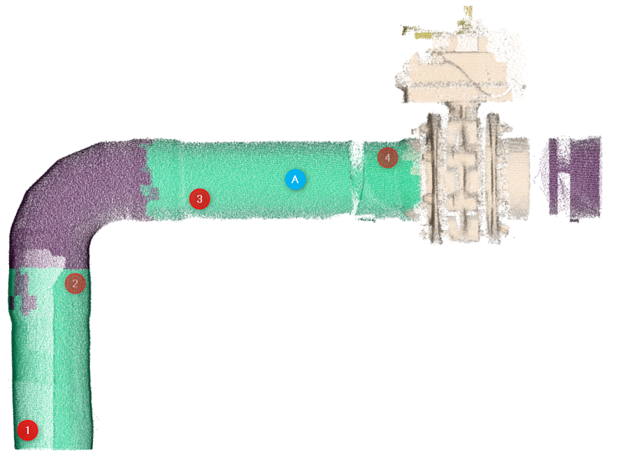
See example below: in that example cloud, the best way to semi-extract the following trace is by extracting a first straight pipe by clicking point 1 then point 2, then continuing with elbow + straight pipe by clicking point 3 then point 4.
Auto extraction:
Clicking on the middle of well-defined and clean consecutive straight pipes (see point A on the example below) will provide the best extraction.