Verticality
A similar method can be used to check the verticality of the tank, by creating vertical sections on the tank.
Show only the mesh “Tank mesh Shell 1”. Select it and launch the function Verticality.
First choose the direction of the sections. They can be created parallel to the axis of the best cylinder computed previously, or can be created perfectly vertically. Choose the second option “Parallel to Z axis (vertical sections)”.
You can choose to use the tolerance defined by the API 653 or give in your own tolerances.
Then define where to create the sections. You can create sections at a regular step all around the tank, or only between given angles. You could also give a list of specific angles where to create sections, or choose the option Click point(s) to visually click on the tank where a section is needed.
Choose the options Regular angle between sections and All around and give a step of 10°. Click Preview to display the resulting sections.
The first section is done on the Orientation Marker defined when creating the project.
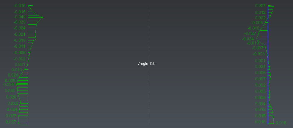
You can now manage the display of the sections to visualize them easily. In Display sections choose the option In a grid to display the sections in 2D in a grid. You can then zoom on one and pan the scene to go from one to another.
You can also choose the option Section by section to visualize only one section at a time. You then have other buttons in the dialog box to switch from one section to the next one.
Click Edit Color to modify the color scale if needed. It is also possible to magnify the deviations in order to see even the smallest ones. Set the cursor on 32 for example.
Then click OK to validate and come back to the previous command.
 Magnify the deviations on vertical sections
At any time it is possible to check the option 3D to visualize the sections in 3D on the tank.
Click OK to validate the results. A new folder called “Verticality” is created in the tree. It contains all the sections per angle (on the tank, on the cylinder and the result of the comparison).