Verticality

images/download/attachments/113546681/CmdTankVerticality.svg

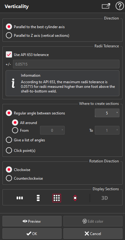
This command allows you to check the verticality of a tank creating:

  • vertical sections on the best cylinder

  • vertical sections on the mesh of the tank

  • inspections between vertical sections on the mesh and vertical sections on the best cylinder

The Best Cylinder must be computed before launching this command.

The mesh of the tank defined for the project is used by default. However, it is possible to create sections on any other mesh by selecting it before launching the command. You can, for example, use only the shell of the tank after using the command Separate Shell.

Note

For a given angle, a comparison will be computed between sections on the best cylinder and on the mesh. The section on Best Cylinder will be considered as the reference. The sections on the mesh will then be colored depending on the deviations found.

images/download/attachments/113546681/image2019-10-24_15-57-58.png

  1. Choose the direction of the axis to use to compute sections. It is possible to use:

    1. the direction of the best cylinder

    2. or the Z direction, to create vertical sections.

  2. Define the Radii Tolerance or use the API 653 tolerance.

  3. Choose where to create your sections:

    • With a regular angle between each section: all around the mesh or on a certain part,

    • By giving a list of angles,

    • By clicking points on the mesh to define where the sections need to be created.

  4. Choose the rotation direction of the sections
    By default, angles are defined in the counterclockwise direction, starting on the reference point defined for the orientation of the project (see Create/Edit Project).

    An angle of 0° creates a section on this reference marker.

    When you define an angle, a section is done on both sides of the mesh, so a section with an angle of 0° will give the same result as with an angle of 180°.

  5. Click Preview to compute the sections and check the results.
    The sections will be previewed in a 2D layout, so that the results can be easily checked. The option 3D allows to split the view vertically, in order to visualize the 3D elements in the left view and the 2D layout in the right view.

  6. If the results are satisfactory, you can edit the colors of the inspection by clicking on the Edit Colors button or validate the results and exit the command with OK.
    At any time, it is possible to stop the current computation with the escape key or exit the dialog box with Cancel.

Create a report

This command automatically creates reporting data images/download/thumbnails/113546262/ReportingDataIcon.png in your document. This object stores your results so as to create a report later.

From the treeview click on the magnifier iconimages/download/thumbnails/113546262/ReportEditorIcon.png to launch the report editor (or launch Report Editor). Then, each object images/download/thumbnails/113546262/ReportingDataIcon.png stands for a chapter which can be added to your report.

Refer to Reporting to learn how to customize your report.