Exercise: create an ortho-image and import it in AutoCAD
Create the ortho-image
Open the file TextureParam&CameraPath.3dr.
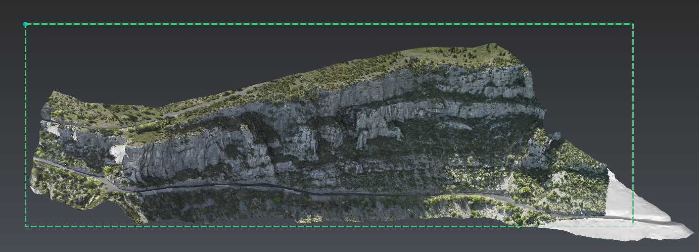
Activate the viewset called "Ortho-image" by clicking on its bulb and launch the command Extract OrthoImage.
Set the parameters as below:
Top left corner position: X=1741310; Y=2298300; Z=673,
Background color: white,
Unit: m,
Width: 600,
Height: 200 (Unlock to keep the width),
Image pixel size: 0.25.
 3D scene
Click Preview to visualize the image and then Save the orthoimage as a picture file (jpg, bmp, ...) and a georeferencing file (txt). In the dialog Select the destination file..., enter orthoimage as file name and choose jpeg as file format.
Two files have been created:
orthoimage.jpg: the picture
orthoimage.txt: the georeferencing file
Insert the image in AutoCAD
Open orthoimage.txt with a text editor like Notepad and an empty file with AutoCAD.
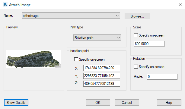
From AutoCAD, enter IMAGEATTACH in the command line prompt and select orthoimage.jpg
Tip & Trick
You can also add a Raster Image Reference... from the menu Insert... or try to find the function from the ribbon.
Uncheck all the options as below. Then copy-paste the insertion point from orthoimage.txt (see the Autocad import section) to Insertion point group. Do the same for the Scale and set the Rotation to 0. Validate with OK.
 Attach Image
Rotate the image in AutoCAD
Now, it is necessary to rotate the image.
Warning
Choose counterclockwise either Decimal Degrees or Radians as Drawing Units (enter units in the command line prompt or launch Units from the menu Format).
Warning
If more than 1 rotation is needed, remember that a first rotation along an axis will modify the 2 others axis. That is why, this exercise shows you the worst case you can find: 3 rotations.
If rotation Z is not 0, enter ROTATE3D in the command line, select the image, select the Zaxis direction, select bottom left corner in image object and copy-paste rotation Z.
Then if rotation X is not 0, enter ROTATE3D in the command line, select the image, use
the bottom left and bottom right points of the image object
to define the rotation axis (X'axis) and copy-paste rotation X.
Finally if rotation Y is not 0, enter ROTATE3D in the command line, select the image, use the bottom left and top left points of the image object to define the rotation axis (Y"axis) and copy-paste rotation Y.
Command: _imageattachCommand: ROTATE3DCurrent positive angle: ANGDIR=counterclockwise ANGBASE=0Select objects: 1 foundSpecify first point on axis or define axis by[Object/Last/View/Xaxis/Yaxis/Zaxis/2points]: zSpecify a point on the Z axis <0,0,0>: Specify rotation angle or [Reference]: 107.6246919131824Command: ROTATE3DCurrent positive angle: ANGDIR=counterclockwise ANGBASE=0Select objects: 1 foundSpecify first point on axis or define axis by[Object/Last/View/Xaxis/Yaxis/Zaxis/2points]: Specify second point on axis:Specify rotation angle or [Reference]: 66.88607460754096Command: ROTATE3DCurrent positive angle: ANGDIR=counterclockwise ANGBASE=0Select objects: 1 foundSpecify first point on axis or define axis by[Object/Last/View/Xaxis/Yaxis/Zaxis/2points]: Specify second point on axis:Specify rotation angle or [Reference]: 2.49350983527415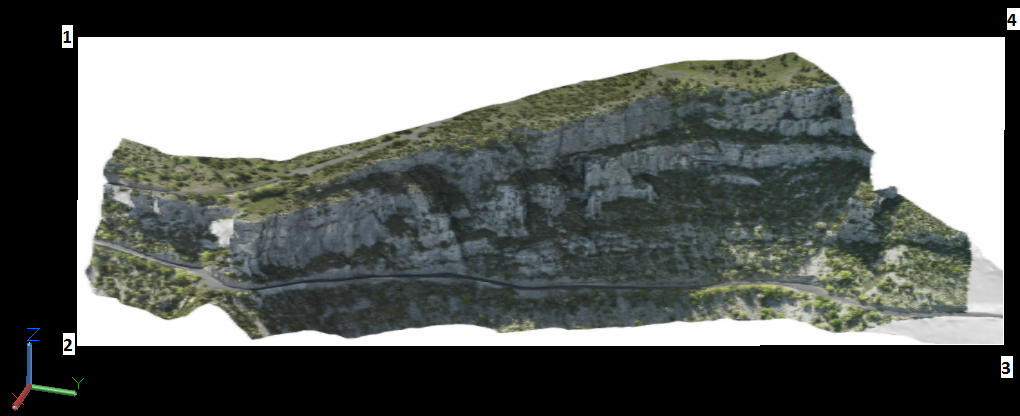 AutoCAD result
You can check the result with corner pixel coordinates (see the Image attributes section in orthoimage.txt).
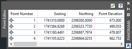 Control points