Extract OrthoImage
![]()
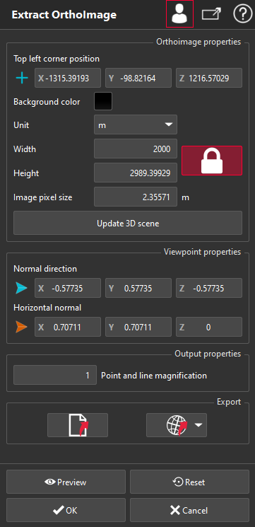
This command allows you to create an ortho-image from the 3D scene. The image can be saved and/or sent directly to AutoCAD.
No selection is required to launch the command but the perspective view must be disabled.
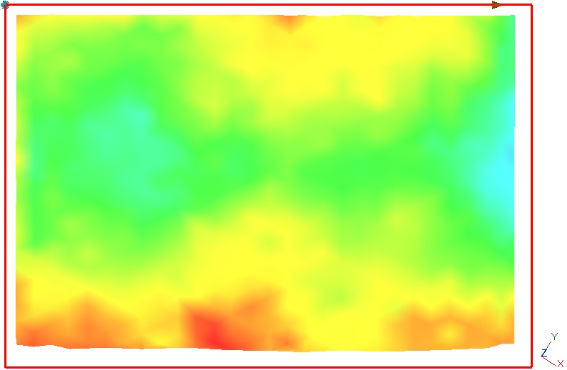
By default the created ortho-image (shown with a red rectangle) represents the whole 3D scene, but can be customized thanks to the dialog box.
|
|
Note In case of saved images, three formats are available: JPEG, BMP and TIFF. TIFF format embed georeferencing information. Note For each saved image, a world file (.jgw, .txt or .tfw) with the same name will be created. This file can be automatically read by most of GIS software. It also contains georeferencing information and tips to import the image in software that does not manage world files. |
Exemple: creation of an image fitted to a non horizontal object
Exemple of world file created with an ortho image
0.17174583809940424661277802442783
0.10248593608653447373235678696801
0.10248593608653447373235678696801
-0.17174583809940424661277802442783
553742.55796354659833014011383057
243915.13328190083848312497138977
[Image attributes]
Unit=m
Pixel Top Left=553742.5579635466 243915.1332819008 65.49000015203238
Pixel Top Right=553957.2402611709 244043.240702009 65.49000015203238
Pixel Bottom Right=554095.5962748878 243811.3838205748 65.49000015203238
Pixel Bottom Left=553880.9139772635 243683.2764004667 65.49000015203238
Normal axis=0 0 -1
Horizontal axis Top Right=0.8587291904970212 0.5124296804326723 0
Image width (pix)=1250
Image height (pix)=1350
Pixel size=0.2
[Autocad import]
Insertion point =553880.9139772635, 243683.2764004667, 65.49000015203238
Insertion point X=553880.9139772635
Insertion point Y=243683.2764004667
Insertion point Z=65.49000015203238
Scale=250
rotation Z (rad)=0.5380118002680606
rotation Z (deg)=30.82580548359529
rotation X (rad)=0
rotation X (deg)=0
rotation Y (rad)=-0
rotation Y (deg)=-0
HOW TO INSERT a JPEG IMAGE IN AUTOCAD
-------------------------------------
1-Insert the image in AutoCAD
Enter 'IMAGEATTACH' on the command line
Select the image file
Enter 'Insertion point X', 'Insertion point Y' and 'Insertion point Z' for the insert point
Enter 'Scale' for the scale
2-Rotate the image (if needed)
2. a. If rotation Z is not 0
Enter 'ROTATE3D' on the command line
Select the image
Select the Z direction
Enter 'Insertion point' to specify a point on Z axis (or select bottom left corner in image object)
Enter 'rotation Z (rad) or rotation Z (deg), depending on defined unit
2. b. If rotation X is not 0
Enter 'ROTATE3D' on the command line
Select the image
Use the bottom left and bottom right points of the image object to define the rotation axis
Enter 'rotation X (rad) or rotation X (deg), depending on defined unit
2. c. If rotation Y is not 0
Enter 'ROTATE3D' on the command line
Select the image
Use the bottom left and top left points of the image object to define the rotation axis
Enter 'rotation Y (rad) or rotation Y (deg), depending on defined unit