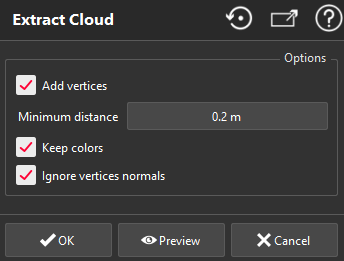
This command converts all polylines, geometrical features, CAD curves and meshes into a unique merged cloud.
This function will create a cloud with all vertices from selected objects. You can also add new vertices to the cloud, by sampling the objects.
Select polylines and/or meshes and/or geometrical features and/or CAD curves and launch the command.
Additionaly, if one or more clouds are selected, they will be added in the resulting cloud.
|

|
Depending on the type of selected object(s), the software extracts all the vertices of the selected entities and merges them into a unique cloud.
The minimum distance allows sampling of points on the selected entities. This value does not define a regular "space" between the points of the generated cloud, but a minimum point density.
If you have more than one input objects, Keep colors
creates a cloud having a
Real Color
representation, where each none
Real Color
input object will transfer its color to their points:
in Real Color representation mode, you will see the colored points.
in Inspection representation mode, you will see the inspection information, if any.
in another representation mode, the color of the cloud will be uniform.
If you have selected a mesh, uncheck Ignore vertices normals to convert current vertices normals into point cloud scanning direction.
Validate the command with OK or display the result with Preview. In this case, all points of selected entities are merged into one cloud. You can also close the dialog box with Cancel.
Note
To generate a cloud from a mesh with a regular space between points, you can use the command Grid projection.
|
