Sections along Curve
![]()
This command computes a set of planar sections along a polyline or a curve. The typical application of this command is to calculate profiles along neutral axis as for example tunnels, springs, etc.
Requirements
Select a curve or a polyline (along which we will compute sections) and all the cloud(s) or mesh(es) on which you want to calculate sections and launch the command.
Choose where you want to draw sections:
With Regular you can define the step between sections and optionally a range using Custom. The range is defined with 2 distances. In both cases, one section will match either the start point or the reference point (if you have checked Pass through).
With a List of distances. You can type distances and/or click points in the scene.
If you are drawing Sections on a cloud:
Define the Slice thickness: the points inside the slice are projected on the median plane in order to compute a polyline.
Define the Chaining distance: these points will be chained when they are closer to that distance.
Check Noise Reduction: to filter noise and to avoid chaining every points.
Check Searching distance to draw the sections only in the curve neighborhood. The value corresponds to a radius.
Sections are computed on planes perpendicular to the curve. Since the curve has been discretized, check Advanced normal computation to smooth it before the normal computation (refer to explanations below).
If the curve is oriented in the wrong direction, use the Reverse axis button.
When the object to intersect has inspection values, you can draw inspected sections directly (refer to the example below).
Notes
All distances you enter in the different fields are curvilinear distances; this means distances along the path or the 3D polyline. The origin point where the curvilinear distance is starting from is the first point of the polyline.
If you check the option Advanced normal computation, the polyline is considered, during the calculation, as "C1 smooth" (its tangency function is continuous). Thus, the command can approximate the tangency orientation on each curvilinear distance.
Technical information
Sections on an inspected mesh
If the sections are computed on the inspected mesh (considered as well as the reference or measure), the sections will keep the inspection values of the mesh. It means that the hair diagram will not be, in most cases, in the plane of the section. It depends on the type of inspection (2D or 3D).
Restriction: when a mesh was colored as the measure with a cloud as reference, this capability is not available.
Example of a hair diagram in 3D on a planar section:
 1. CAD and mesh used to compute the inspection
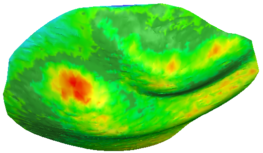 2. 3D Inspection with colors applied on the 3D mesh
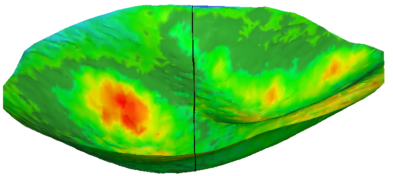 3. Section on the inspection mesh (Y plane)
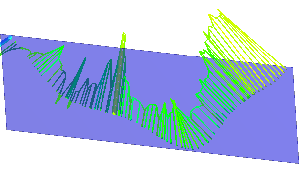 4. Plane Y and hair diagram in 3D: direction of the deviation
If you want to have a hair diagram on the plane of the section:
Do an inspection in the direction of the plane and then do a section with this plane.
Do a section in the plane on both entities (reference and measure) and then do an inspection of this polyline/set of polylines.