Freehand Sections
![]()
This command computes one or several sections on one or several meshes on one plane. It also allows you to draw projected polylines on meshes.
Requirements
Select the mesh(es) on which you want to calculate a section and launch the command.
Best plane
When using the first option, the plane is defined by the best plane of the clicked points:
Click two points on the plane. If the points are clicked on the mesh, the projection on the mesh is assumed. Once you have clicked the first two points, the software calculates the first section assuming the plane is perpendicular to the screen view.
Click other points. Every time you click a new point, a best plane is computed and the section is updated.
Projected segments
When using the second option, segments are recursively projected (indefinitely repeated) while the user clicks new points:
Click two points on the mesh(es) or on the view. Once you have clicked the first two points, the software calculates the projection of the segment defined by the two points onto the mesh(es) according to the screen view direction.
Click other points. Every time you click a new point, the software calculates the projection of the segment defined by the last two clicked points onto the mesh(es) according to the screen view direction.
Notes
The result is one set of polylines or one polyline that you can explode in several segments with Ungroup Polyline function or separate with Cut Polyline function depending on your needs.
You can use the freehand sections in order to separate a mesh (Constraint Mesh), to prepare a polyline for further sharp edge reconstruction (Sharp Edges), or to create a polyline network for CAD surface reconstruction.
Tips & Tricks
At any time, you can remove the last clicked point by pressing Del or Backspace key.
Press the C key to close the current polyline.
Technical information
Sections on an inspected mesh
If the sections are computed on the inspected mesh (considered as well as the reference or measure), the sections will keep the inspection values of the mesh. It means that the hair diagram will not be, in most cases, in the plane of the section. It depends on the type of inspection (2D or 3D).
Restriction: when a mesh was colored as the measure with a cloud as reference, this capability is not available.
Example of a hair diagram in 3D on a planar section:
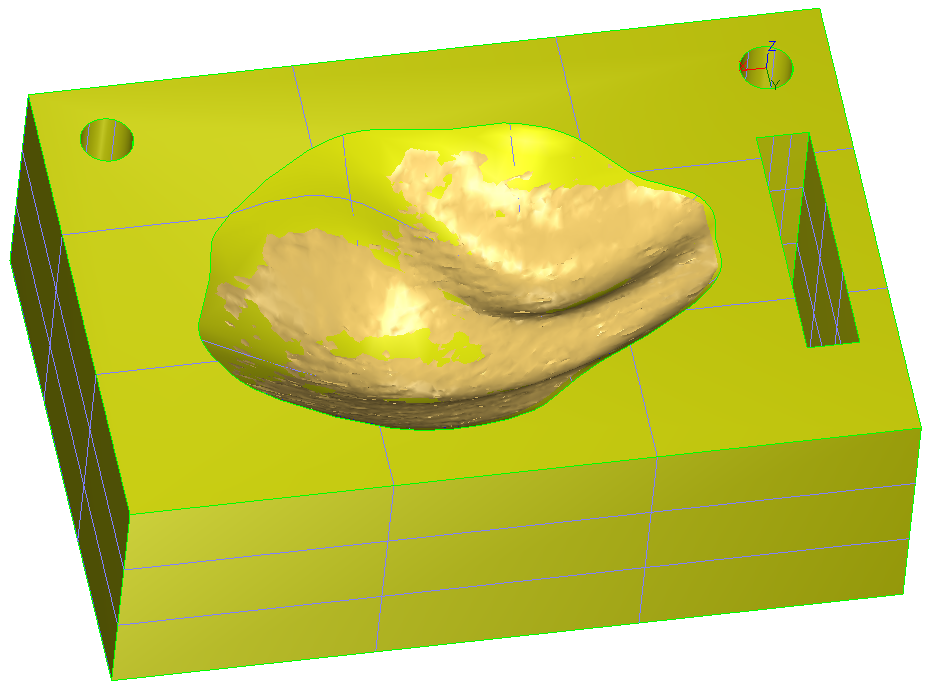 1. CAD and mesh used to compute the inspection
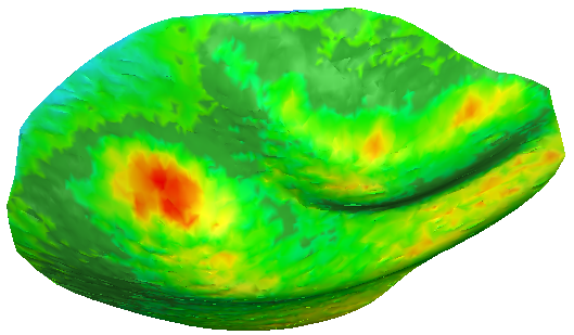 2. 3D Inspection with colors applied on the 3D mesh
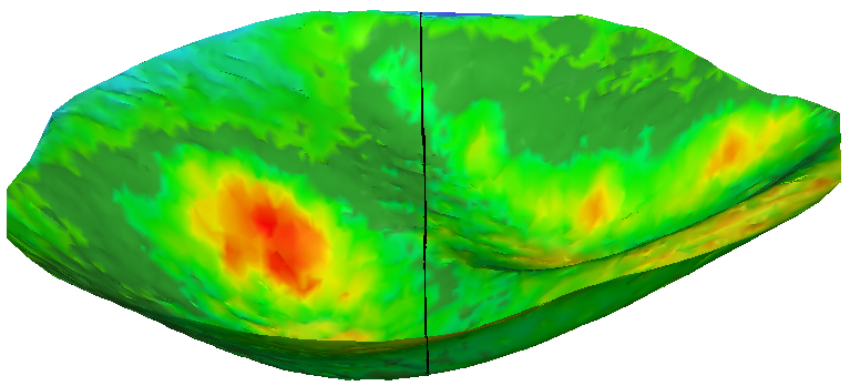 3. Section on the inspection mesh (Y plane)
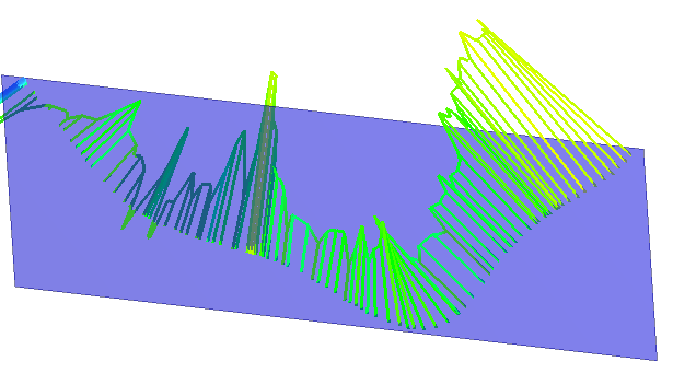 4. Plane Y and hair diagram in 3D: direction of the deviation
If you want to have a hair diagram on the plane of the section:
Do an inspection in the direction of the plane and then do a section with this plane.
Do a section in the plane on both entities (reference and measure) and then do an inspection of this polyline/set of polylines.