Create Profiles along Axis
![]()
This command creates cross sections on an object (mesh or point cloud) along a polyline. This polyline should be the neutral axis of the object. This command allows to preview the cross sections in a 2D layout, so that they can be more easily checked.
Select the polyline and the object (mesh or point cloud) on which to create the sections. Two objects (mesh or cloud) can be selected in order to create sections on both at the same time with the same parameters. Then you can launch the command.
Curvilinear distances: choose whether the distances entered are expressed in 2D (only taking into account X and Y coordinates), or in 3D (X, Y, Z).
Orientation of the sections: choose to create sections in vertical planes or in planes locally perpendicular to the neutral axis.
Check the direction of the axis with the arrows displayed and click on Reverse Axis if necessary.
Select, if necessary, the option Remove points distant of more than to cut the sections in width and height. The input value is a maximum 3D distance threshold around neutral axis.
Choose where to create the sections:
With a regular step between profiles (curvilinear distance between sections): all over or on a certain part,
List of distances from the point starting with the first point of the axis (you can separate your values with a comma, a semicolon, a space, etc.).
Click point(s) then select where to create sections with Define points. If the selected points are not on the axis, they will be projected on it (shortest distance).
Set the names of the cross-sections (Naming): a name will be assigned to each section, composed of the Prefix and the distance of the section from the first point of the axis.
Prefix: choose the prefix for the distance information. In a tunnel for example, distance are given with the prefix "MP" for "Milepost." You can also define an offset to add to the names.
Offset: value added to the position of the section.
Click Preview to compute and check the results.
Choose how to Display Sections:
In a line,
In a column,
In a grid,
Individually,
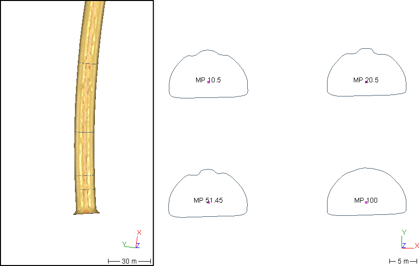
The option Show a 3D view allows splitting the view vertically, in order to visualize the 3D elements in the left view and the 2D layout in the right view.
If the results are satisfactory, there are three possibilities:
Compare/Inspect the cross sections: go directly to the command Compare / Inspect Profiles.
2D Preview/Export to export the cross sections in their 2D layout.
OK: validate the results and exit the command.
At any time, it is possible to cancel the current computation (by ESC) and exit the dialog box with Cancel.
Note
If sections are being created on a point cloud, more parameters need to be filled:
Noise reduction: activate to keep only the best points of a section.
Plane thickness: all points between two parallel planes, distant from this value, belong to the section.
Chaining distance: if the distance between two neighbor points is less than this value, a segment is created.
2D preview for sections
Create facade cross-sections
You should define an User Coordinate System with Z axis perpendicular to the wall and Y axis vertical. Then, the cross-sections axis must be defined from the top to the bottom. Otherwise, you can click on the Reverse axis button.