Compare / Inspect Profiles
![]()
This command allows comparing sections by pair. To keep the compatibility between sections, they should be generated using the command Create Profiles along Axis. This command gives new lines with colorized segments, showing the differences between two profiles. These differences may have positive or negative values.
Select the sections to compare. It is possible to select several pairs of sections. They will be compared together (if their names match: same basis. Only the number at the end changes). Then launch the command.
Choose the Inspection Type:
Tunnel (3D inspection): The software will project points of the measured sections onto the reference sections in 3D (shortest distance between reference and measure). Choose this option if sections are closed or have a circular shape, for instance, for making a comparison between a theoritical and a has-built tunnel.
Road (2D inspection: along a direction): The software will project points of the measured sections onto the reference sections using the given direction. Choose this option if sections are linear, for instance, for making a comparison between a ground and a road project (giving Z as direction).
Choose the Reference sections.
Other sections will be considered as the measured sections. To compute the distances between sections, points on measured sections will be projected on the reference sections. Measured sections will be colored.
Choose the Colors for the Overbreak and Underbreak deviations in order to easily localize the parts where the measured section is over or under the reference section.
Colors for overbreak and underbreak are available only if the colormap is made with 2 levels separated by the threshold 0. Otherwise color buttons are disabled and you have to use Edit Color to change the colormap (see Edit Colors).
Click Preview to compute and visualize the results.
At the end, you can either click on:
2D Preview / Export: to go directly to the command 2D Preview/Export and export the 2D layout
OK: to validate and exit the command
Cancel: to cancel the computation and exit the command
The cross sections will be displayed in a 2D layout, so that the results can be more easily checked than in 3D. The button 3D allows to split the view vertically, in order to visualize the 3D elements in the left view and the 2D layout in the right view.
Quotations
You can improve the quotation texts:
using Advanced parameters:
remove the quotations where deviations are greater or lower than a certain value
remove the quotations for the parts under a certain height over or below the axis point (ignore the road filter). This option is suitable to filter road values (3D inspection only)
write quotations around the axis with a regular step (angle or length for Tunnel 3D; length for Road 2D)
using Edit color.
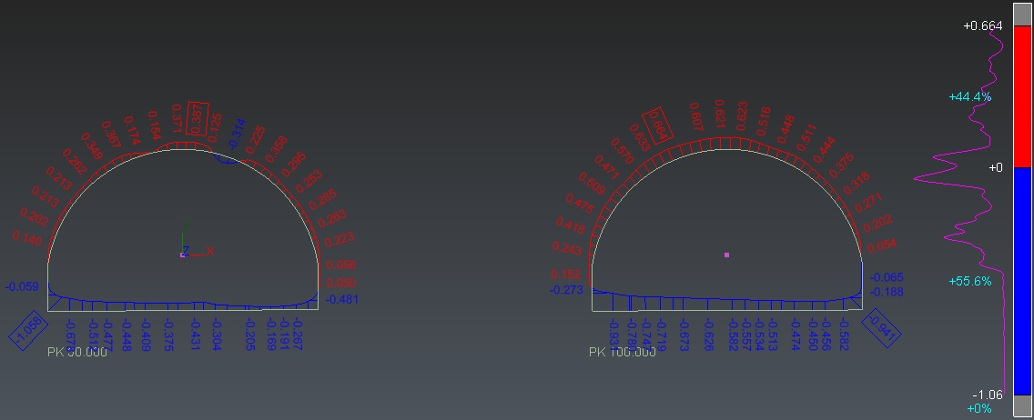
Comparison between two sections
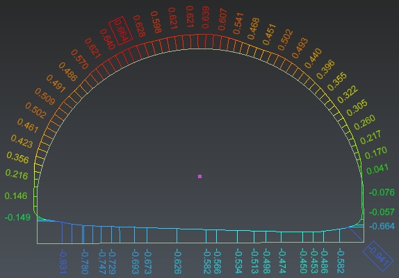
Overbreaks and Underbreaks on sections