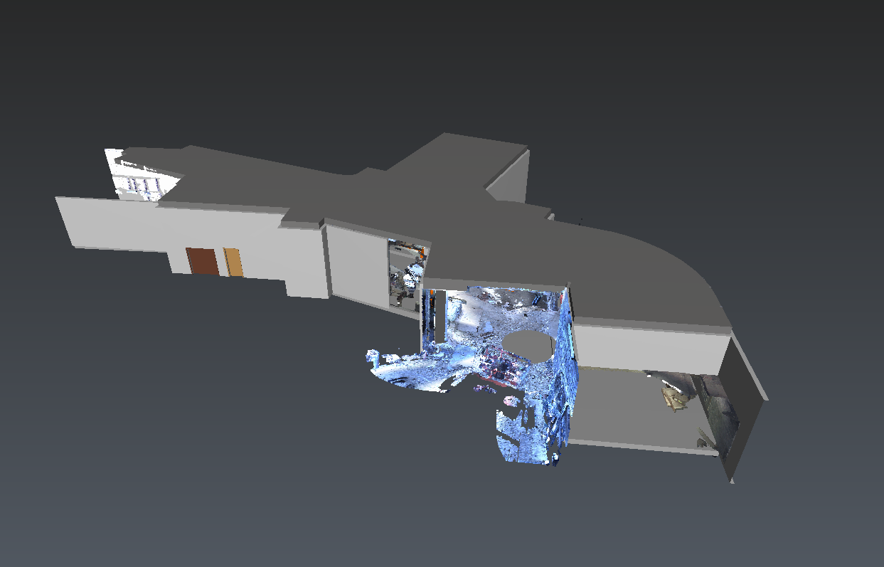
Inspect the scanned data with the BIM object
Start the software in Touch Mode.
Ideally, you would follow those steps using a touch device.
Start a new workflow (LOAD)
Start a new BIM Inspection workflow.
Select BIMInspectionPreparationfile.3dr as the preparation file
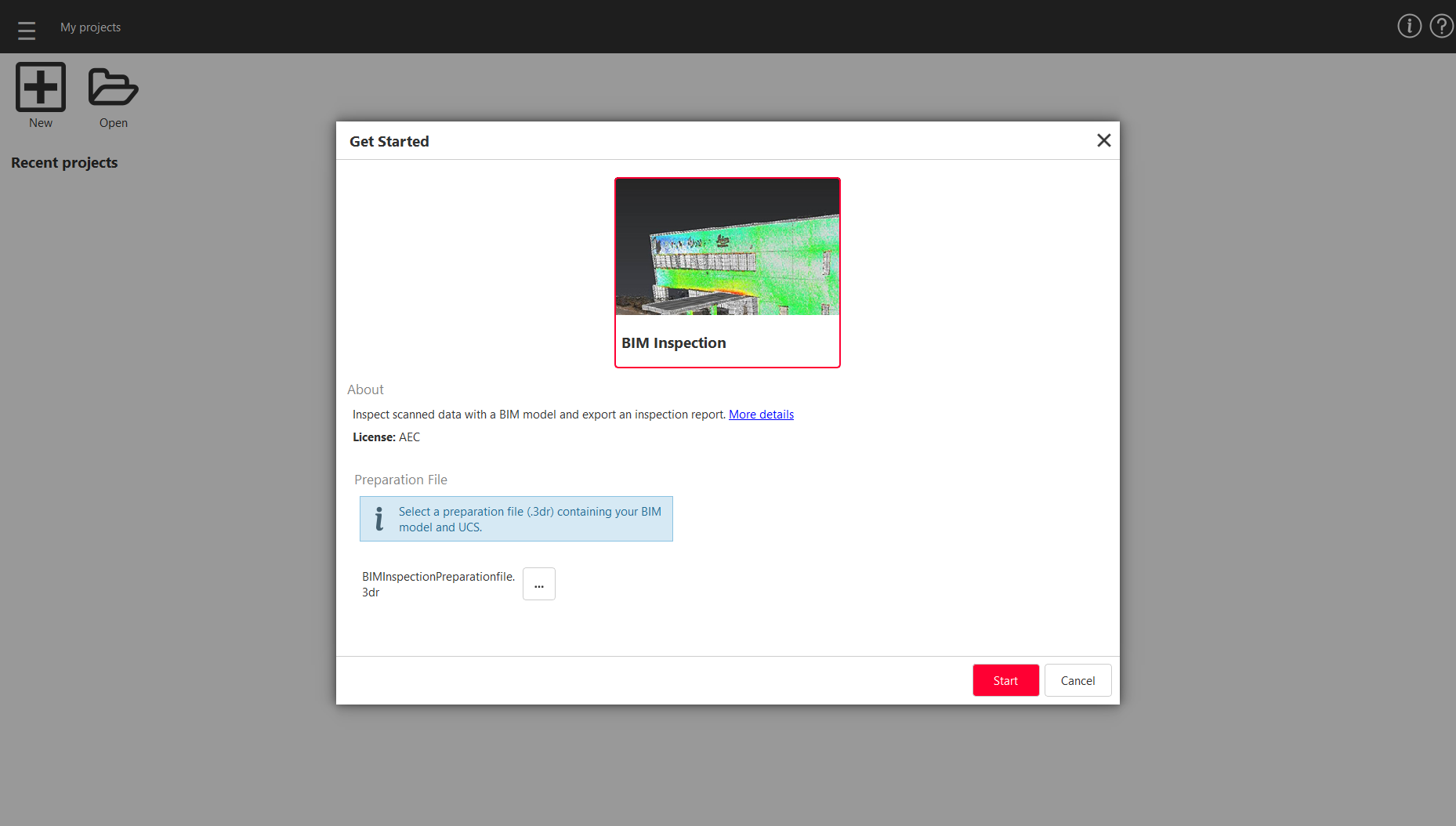 Get Started
Follow the workflow instructions and load the site object, corresponding to site BIM model and import the scan from the file site.e57 then click on Next.
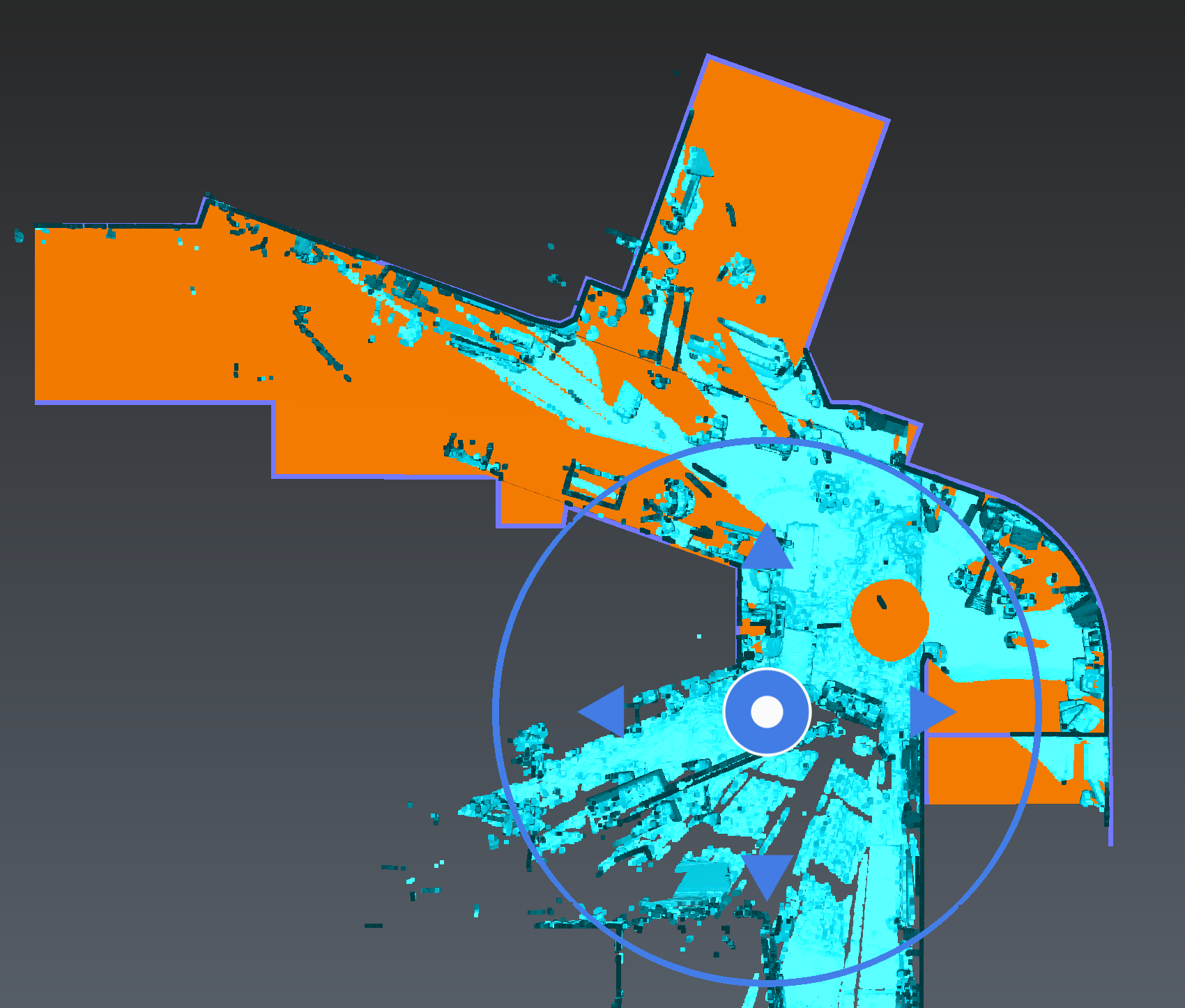
Align model and scanned data (PREPARE)
Both objects are not aligned together. For instance, choose to move the cloud toward the BIM model (select Scan to BIM Model at the startup of the alignment step).
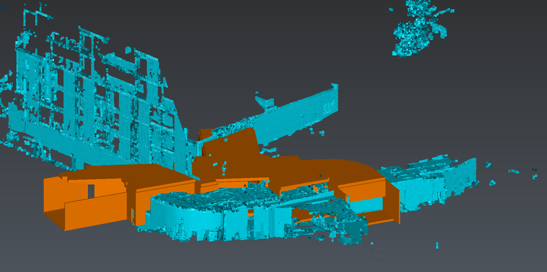 Both objects are not well aligned
Then, you can align manually the cloud more accurately.
Start using the Top Ortho view: either translate or rotate the cloud in 2D.
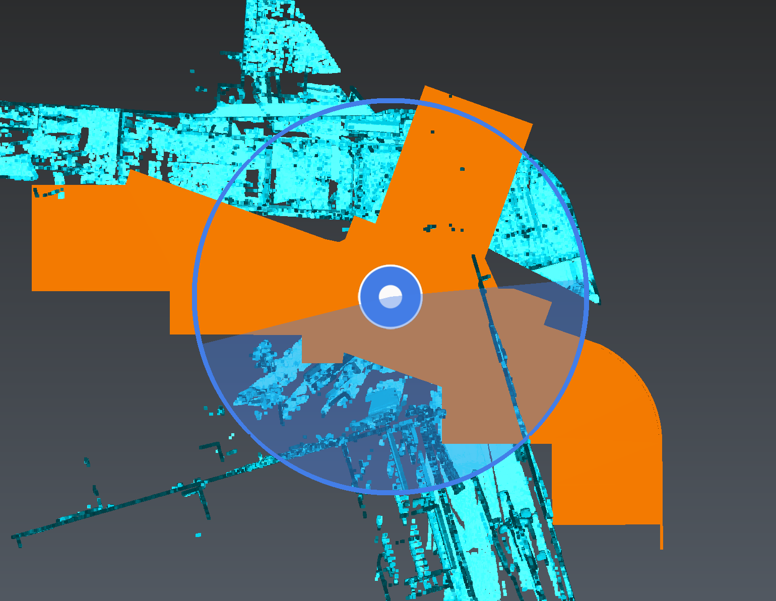
Activate a limit box centered around the BIM to ease camera movements:
Hide the scan
Display the Quick Access toolbar and activate the limit box, then close the limit box edition
Show again the scan
Switch to Front Ortho view: either translate or rotate the cloud in 2D.
Switch to Orbit Ortho: check that both objects are well pre-aligned. If not, repeat steps 1 & 3.
If the manipulator is not centered enough, you can relocate it.
The manipulator is displayed depending on zoom factor.
 Move the cloud manually (a)
Tap on the screen to display the quick access toolbar, then tap the limit box icon to create and adjust it. Limit boxes are initialized thanks to displayed objects bounding box and UCS orientation.
 Adjusting the limit box
 Move the cloud manually (b)
Set the best-fit settings:
Preserve Z axis orientation: checked.
Best Fit Attraction: 5 cm. Both objects have to be closer than this threshold before computing the best fit.
Finally, perform the best fit, check the mean value error and validate this step.
The Best Fit tolerance can be set through specific settings (BIM Inspect Specific Settings, BIM inspection tab).
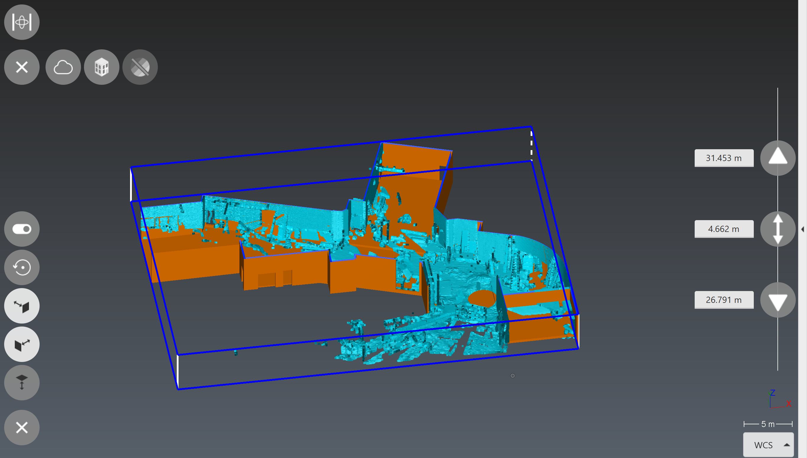
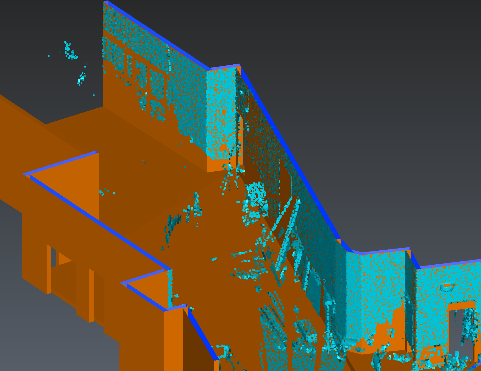 Both objects are now well aligned
Clean the point cloud (PREPARE)
Usually and especially with terrestrial laser scanners measuring full domes, you will acquire areas you are not focusing on. In order to deal with tablet specifications, which could be very low compare to your everyday workstation, it is recommended to remove these areas.
Note that another setting, which limits the amount of imported points, can be managed thanks to BIM Inspection settings.
You can remove points:
far from the selected BIM model
clipped by the active limit box
Here, remove clipped points farther than 3 m.
 Cleaned scan
INSPECT
In this exercise we will focus on inspecting columns.
Select the parts to inspect, that is to say the columns, then compute the inspection excluding points farther than 0.2 m and keep the 3D deviation option.
Finally, customize the color mapping as you wish (for instance: tolerance +/- 0.02 m and origin 0).
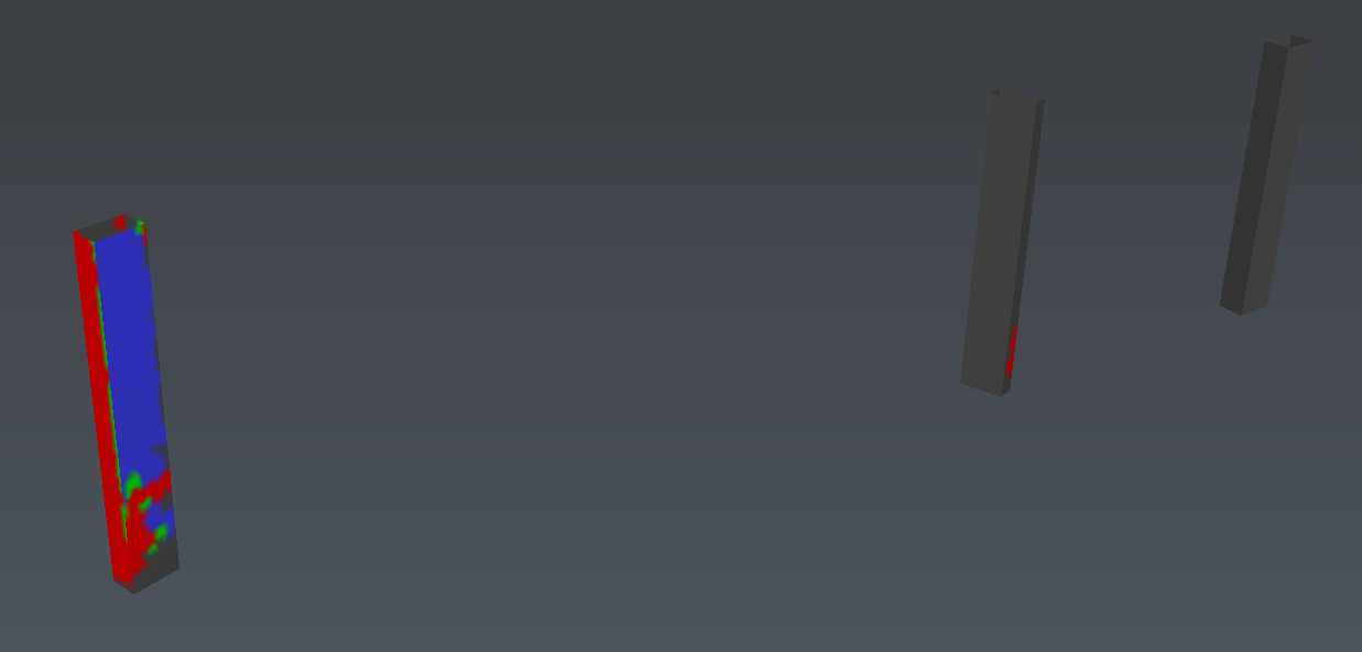 Inspection
DELIVER
In order to provide a report, add notes for each identified object with defection.
In this sample, only one column has issues.
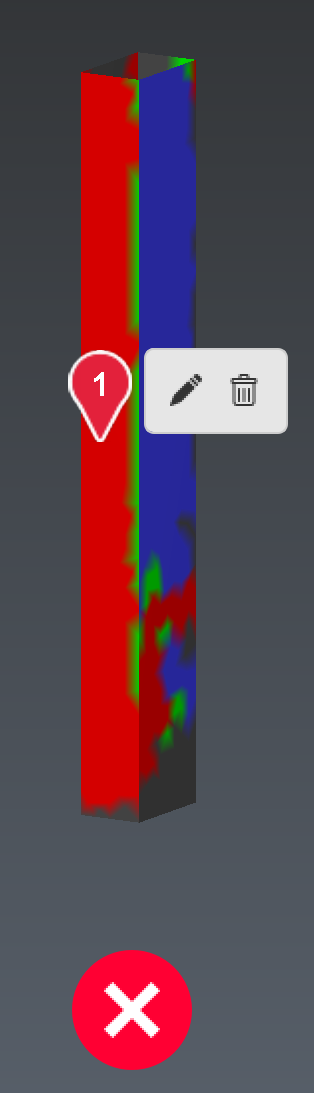 Add a note
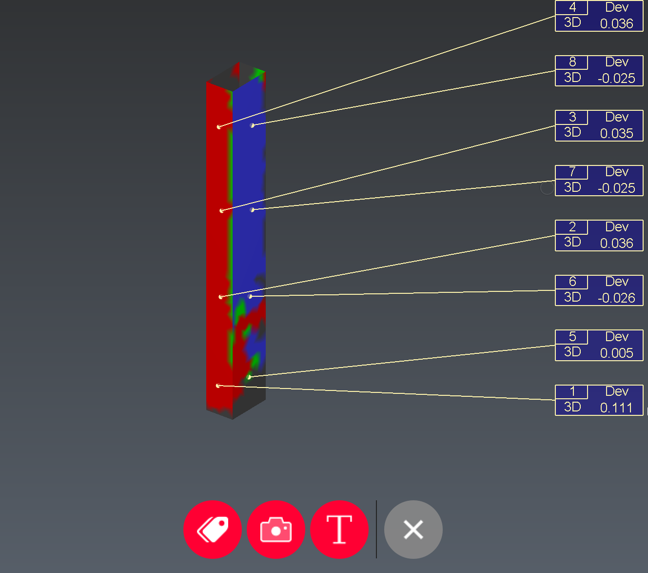
Each note can gather inspection views with deviation labels, photos and comments.
 Edit a note