Exercise: Compute inspection between polylines
Open the file CrossSections.3dr
It contains:
the mesh of a measured tunnel
a theoretical section of the tunnel at a given kilometric point
Select and show these two elements only.
Create a section of the measured mesh
As a first step, we will create a section of the measured mesh in the same plane as the theoretical section:
Select the mesh and launch Planar Sections,
Define the axis of the plane used to compute sections, choose the
 option and click on the theoretical section,
Select the option List of values and click a point on the theoretical section,
Click OK. A section named Planar Section 232.26 is added in the Planar Sections group.
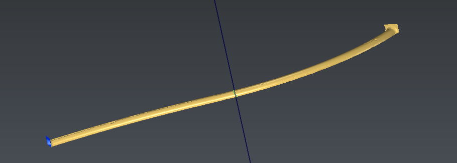 Section on the measured mesh
Inspect the polylines
Select and show only the two polylines Theoretical section and Planar Section 232.26. Select first Theoretical section, as it is the reference, and then select Planar Section 232.26 with CTRL, as it is the measure.
Launch the command Compare Inspect Section vs Section.
Choose to apply the color on the reference object.
Click Preview to compute the inspection, then click on Edit color to magnify the distances. Set Magnify to 11.
Click OK to validate the display. Then, click OK again to validate the inspection. A new object called Comparison Theoretical section / Planar Section 232.26 is added in the Compare Inspect group.
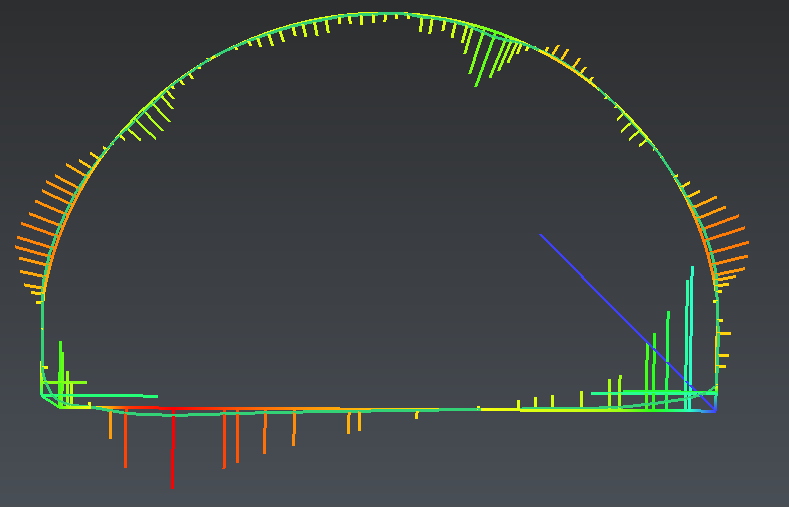 Inspection between two polylines