Exercise: Create a planar section on a point cloud
Open the file SectionsBuildingPlan.3dr
It contains a point cloud of the ground floor of a building. The inner points have been removed in order to lighten the file, only points around the walls have been kept. We will use this example again in the following paragraphs to show how to create the 2D plan of the building.
Select the point cloud and go to Planar Sections.
Choose Z for the plane direction.
Choose List of values.
To define the section plane, place the mouse in the scene and press X on your keyboard to set the view along X axis. You may need to press also A to make a zoom all. Click on ![]() in the dialog box and zoom in the scene to click a point on the top of the point cloud (you can use Nearest 3D Projection in the point selection ribbon). For example, the Z value should be 19.65684 m.
in the dialog box and zoom in the scene to click a point on the top of the point cloud (you can use Nearest 3D Projection in the point selection ribbon). For example, the Z value should be 19.65684 m.
To create sections on a point cloud, additional parameters have to be entered:
The slice thickness gives the thickness of the point cloud to take into account to create the sections.
The chaining distance: if the distance between two points is lower than the given chaining distance, a new segment is created.
These parameters have to be entered regarding the density of the point cloud, and the average distance between the points. Check Noise Reduction in order to have smoother polylines.
You can try different values for the plane thickness and the chaining distance to compare the different results.
From the top view (press Z).
|
Case 1:
|
Case 2:
|
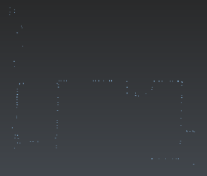
Case 3:
|
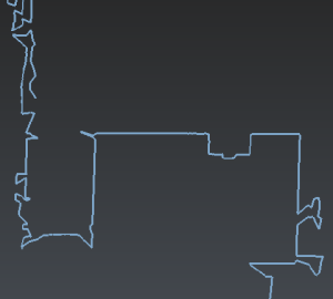
Case 4:
|
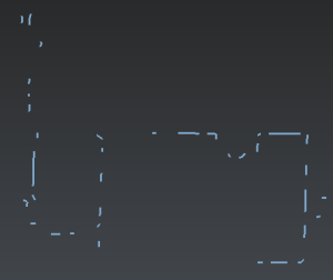
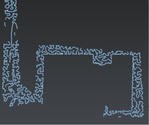
If you enter a plane thickness too low, there will not be enough points, so you will have very short polylines as in above picture (case 1) and you can lose some details. If you enter a plane thickness too high, the points on the floor will be taken into account, so you will have very noisy polylines as in case 2.
If you enter a chaining distance too low, you will have many short independent polylines as in case 3. If you enter a chaining distance too high, all the points will be chained together as in case 4. You will obtain long polylines and you may need to cut them for further processing.
For this exercise:
Set Slice thickness to 0.35
Set Chaining distance to 0.5
Check Noise reduction.
Click Preview and OK to validate the results. A new folder containing all the polylines is created.
Please see the Manage Polyline and Improve Polyline sections to see how to manage and improve the polylines in order to create the 2D drawing of the building. Look at the picture below to see an example of result. The reduced point cloud is blue and the 2D polylines are red.
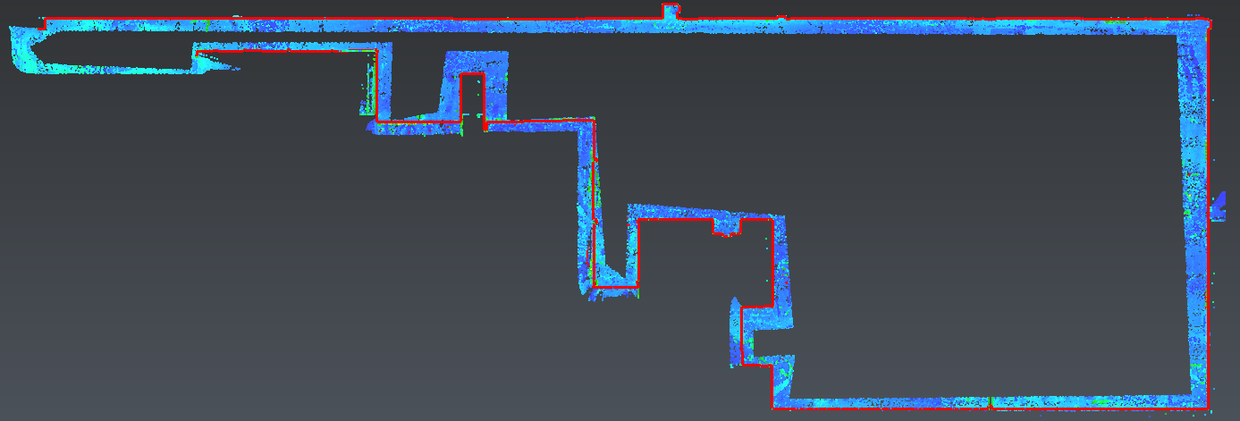 2D plan of a building