Meshing a facade point cloud
Introduction
In the software, several meshing commands are available. The combination of these commands provides many different meshing strategies.
Here, we will show an example coming from a facade which is difficult to process for several reasons:
The cloud is noisy.
The cloud contains many missing parts (holes).
The shape is very detailed but some details have the same size as the cloud noise.
Note that there is another example, named Victory, based on a point cloud of the Samothrace victory (famous statue in the Louvre museum in Paris), which is a very noisy point cloud representing a smooth surface. Then, another strategy is used in the case of this statue.
Exercise overview
In this exercise, we will see how to mesh point cloud:
Make a first mesh to see what happens and decide the strategy to use.
Make a very rough mesh without hole.
Refine taking directly the points of the cloud.
Refine interpolating new points.
Recalculate the sharp edges.
The file used in this tutorial is Facade.3dr.
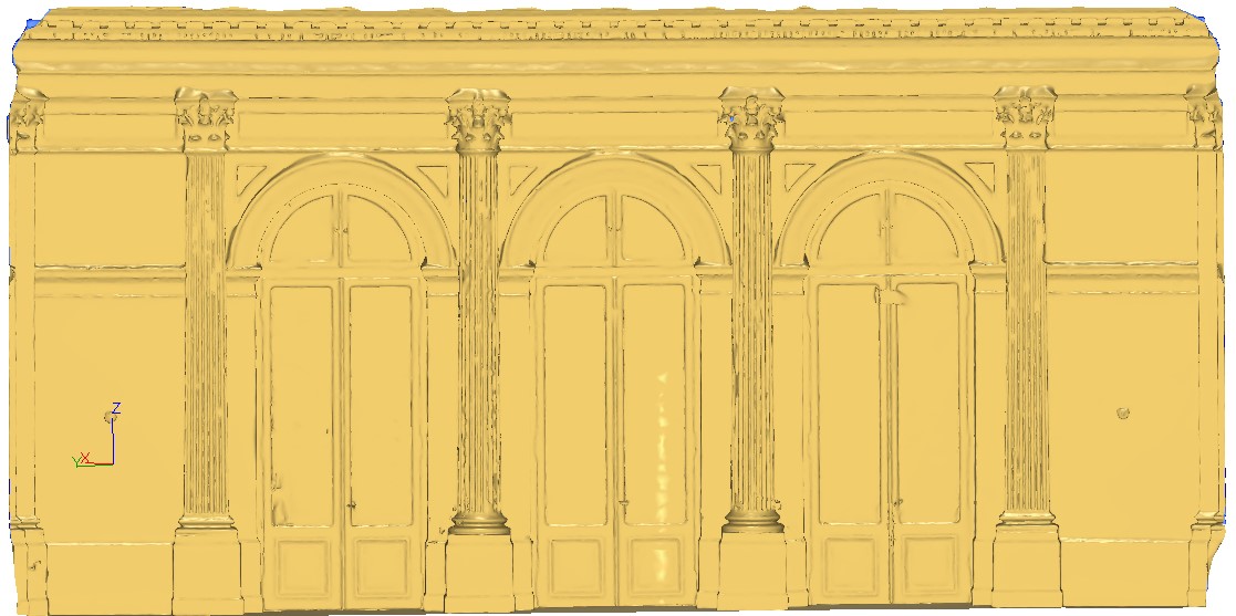
Observe the aspect of the point cloud. The points distribution is not uniform and there are many missing parts, but these areas should not be interpreted as real holes.
Make a first mesh to see what happens
Generally when opening a new cloud, it is difficult to know what the meshing parameter ideal values are. When you enter inside the command 3D Mesh, the software computes parameters for you to get a result in less than 30 seconds regardless of your point cloud size. These “default” parameters usually give you good results but need sometimes to be adjusted according to your model and your expectations.
Select all the clouds that you see on the screen with a rectangle. The clouds will be automatically merged together.
Launch the command 3D Mesh.
Select options Regular sampling and Hole detection with their default values.
Click Preview. The first mesh should arrive in less than 30 seconds. Validate with OK.
When the mesh is on the screen click the right button to select the representation Flat, to better visualize the result without artifacts from the smoothing routines of your graphics board.
You are now ready to analyze your first result. After a quick look, we remark that:
Many holes are present in zones where there is no point.
The complex shapes of the top of the pillars are difficult to mesh and leave holes.
The level of details is insufficient.
The surface is quite faceted and not smoothed as it should be.
The conclusion of this first test is:
We need a bigger triangle size to avoid holes.
We need smaller triangles locally, where a higher level of detail is required.
The problem is that these two requirements are not reconcilable. As a consequence, we will not be able to deal with these two problems in the same step. We should, therefore, first create a rough mesh without holes and then refine the mesh locally using the original point cloud. We can memorize that it is always preferable to start with a mesh having the desired topology and to refine it than to fill the holes of a fine mesh.
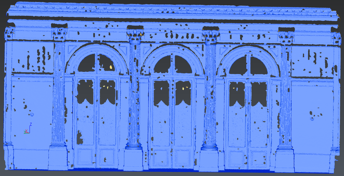 Figure 1: Making the first mesh with the default parameters to see what happens.
Make a very rough mesh without hole
The conclusion of the previous test is that the mesh should be created using larger triangles to avoid holes in the first place. Thus, we repeat the meshing using our original point cloud and only adapt the parameters of the process:
Make an undo (CTRL-Z).
Select again all the clouds that you see on the screen with a rectangle.
Launch the command 3D Mesh.
Options Regular Sampling and Hole detection are selected.
Enter 0.2 m in the field Average distance between points. The software automatically recalculates the Triangle size and the resulting value should be high enough to fill all the holes.
Click Preview to start the meshing.
Validate the result with OK.
The level of detail is, as expected, worse than our previous result but most importantly the surface has the right topology (no hole).
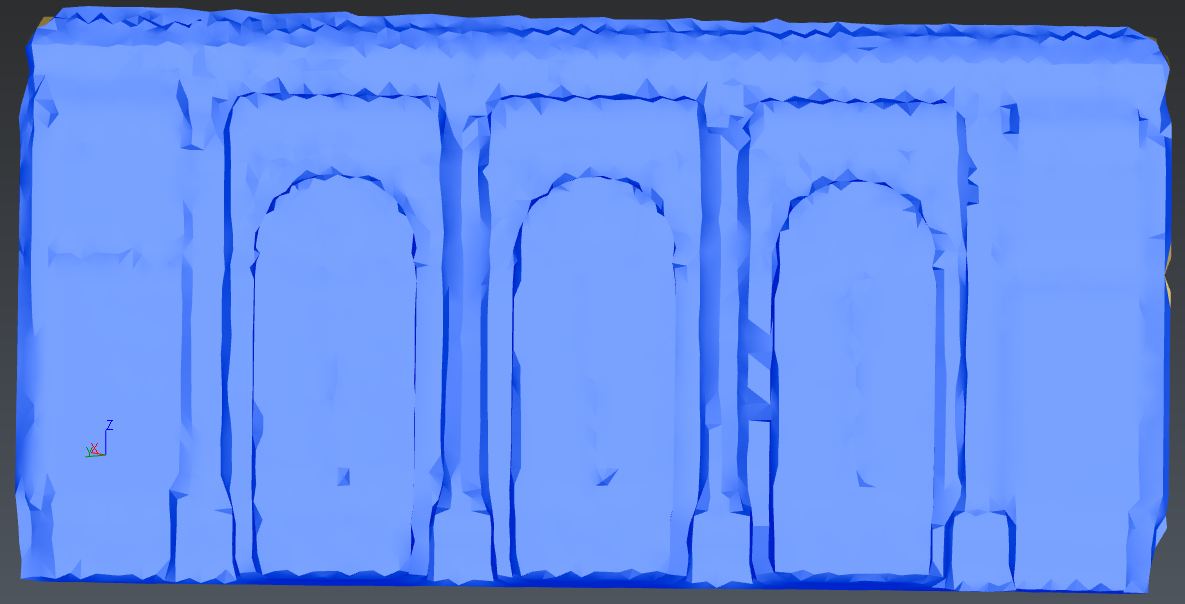 Figure 2: Meshing the facade points of 0.2m. The result has no hole and is a good starting point to start a refinement.
Refine taking directly the points of the cloud
As we have seen, our rough mesh has the desired topology but its level of detail is very poor. We are, therefore, going to refine it locally using the points of the original point cloud:
Select the mesh and all clouds.
Launch the command Refine Mesh from Cloud.
As the point cloud contains a high number of noisy points, we will use the option Keep only best points and choose an error of 5 mm.
Put 0.2 m as Distance because it was the value in the previous step.
Choose No free border modification.
Click Preview.
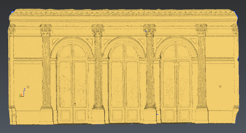 Figure 3: Refining the mesh using directly the points of the cloud to include all the details needed for the future step.
The result is very faceted, spiky and noisy, however if you use a “standard” smoothing as shown in the following picture (Global Smoothing), you will see that most of the unattractive noise can be removed.
Unfortunately, this smoothing tends to deform the model and to transform the sharp edges in radii. We will discard this result, since there is a better way to get a nice smooth mesh which is truthful to the data.
Cancel this operation.
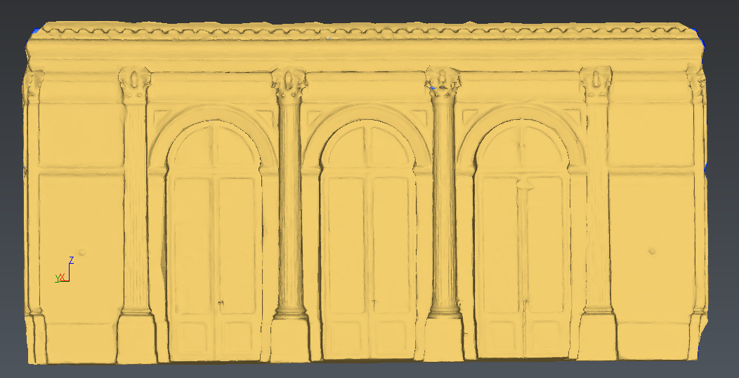 Figure 4: Using the standard smoothing removes most of the noise but the deformation of shape is too high.
Refine interpolating new points
Since all the details are already present in the mesh, even if it looks noisy, we are now going to optimize this mesh by finding the “best” smoothed surface in the middle of the noise thickness.
Select the mesh and all the clouds.
Launch the command Refine Mesh from Cloud Interpolation.
Choose Refine with deviation error.
Enter 1 mm as Deviation error and 5 mm as Minimum triangle size.
Don't generate more than 1 million of triangles.
Check Distance and enter 0.1 m.
Check Local reorganization.
Choose No free border modification.
Click Preview. The result should be considerably nicer than the result before.
Validate the result with OK, Exit.
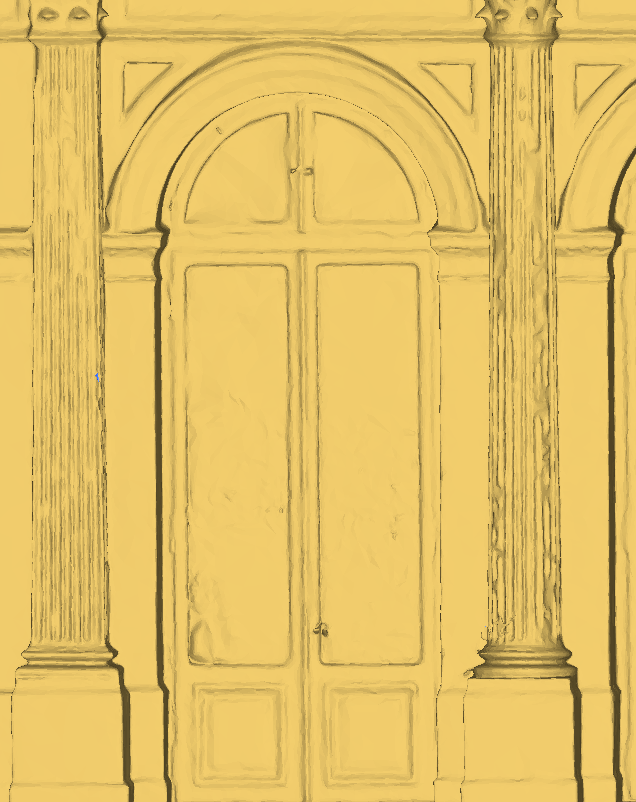 Figure 5: Interpolate new points produces a nicer result.
Recalculate the sharp edges on the pillar corners
Some pillar corners may be rounded and it is possible to make these corners perfectly sharp.
Launch the command Region Grow Plane.
Click on the plane of the most rounded pillar.
Adjust the Extraction tolerance around 2 mm.
Click OK, Next.
Click to extract the second plane of the pillar side.
Click OK, Exit.
Launch the command Intersection and click on the 2 planes to get the intersection line.
Select the line and launch From Geometry to create the corresponding polyline. Choose Deviation option.
Select both the polyline and the mesh and launch the command Sharp Edges.
Choose 0.1m as Cleaning Distance.
Click Preview.
The mesh has been modified to follow the selected polyline.
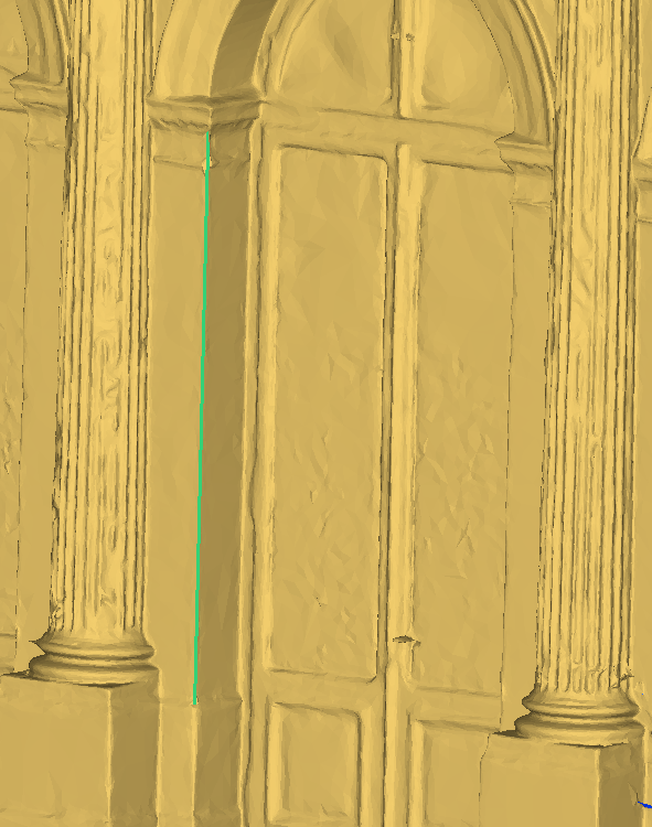 Figure 6: Recalculte sharp edges to follow an extracted polyline.
Recalculate the sharp edges over the vault
Select the mesh.
Launch the command Single Breaking Line.
Choose Only concave or only convex and then, click on the starting and ending point of the vault as shown on the following picture.
Click Ok, Exit.
Now, select the polyline and launch Smooth Polyline.
Choose Hard smooth, with 10 as Smoothing intensity. Click OK.
Select both the polyline and the mesh and launch the command Sharp Edges.
Choose 0.1m as Cleaning Distance.
Click Preview.
The mesh has been modified to follow the selected polyline.
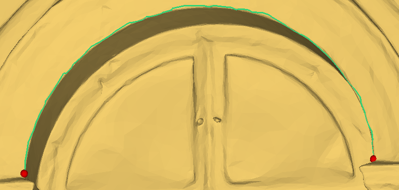 Figure 7: Use feature lines, to extract the borders of the vault.
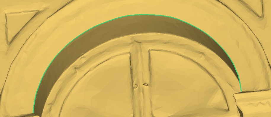 Figure 8: Reconstruct the perfect sharp edge of the vault.