Tunnel inspection and animation
Introduction
In the software, you can process a tunnel inspection thanks to several commands:
Compute neutral axis,
Create profiles along an axis,
Compare profiles,
Print in a specific template,
Compute volumes of overbreaks and underbreaks,
Create a 2D inspection map,
Create a video animation.
The file used in this tutorial is TunnelInspection.3dr
Computing the neutral axis of the tunnel
First we need to reconstruct the neutral axis of the tunnel.
Select the mesh and launch the command Neutral Axis.
Choose Circle section, don't define the diameter, and uncheck both Reconstruction options as we don't need to reconstruct the tunnel. Click on Preview to see the resulting neutral axis.
Click on OK to validate the axis in the scene.
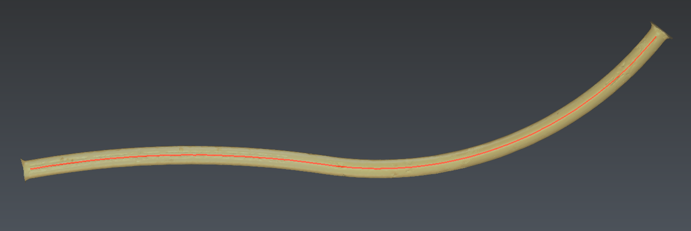 Figure 1: Neutral axis of the tunnel.
Creating the theoretical model of the tunnel
In order to inspect the mesh of the measured tunnel, we will create the mesh of the theoretical tunnel.
Hide the Measured tunnel.
In the contour group, show the Theoretical section and select it.
Launch the command Profile along a Path.
Select the neutral axis. The section will be extruded along it.
Tick the option Turn with the curve.
Set the profile base point in the middle of the profile
Press Preview and OK to create the mesh.
You can rename this mesh as Theoretical tunnel.
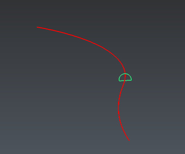 Figure 2: Creating the theoretical model by extrusion of a theoretical section along the neutral axis.
Creating profiles along the neutral axis
Now we will create profiles on both meshes in order to compare them in the next step.
Select the mesh of the measured tunnel, the mesh of the theoretical tunnel and the neutral axis.
Launch the command Create Profiles along Axis and set the following parameters:
Curvilinear distance: 3D
Orientation: Locally perpendicular
With a regular step: 25
From 10 to 500
Prefix: MP
Offset: 0
Press Preview to create the profiles. Profiles are displayed in a 2D layout. You can show them in 3D with the option 3D.
Then press OK to create the profiles and leave the command. You can also press Compare/Inspect to go directly to the next step.
A new folder containing all the profiles is created in the tree.
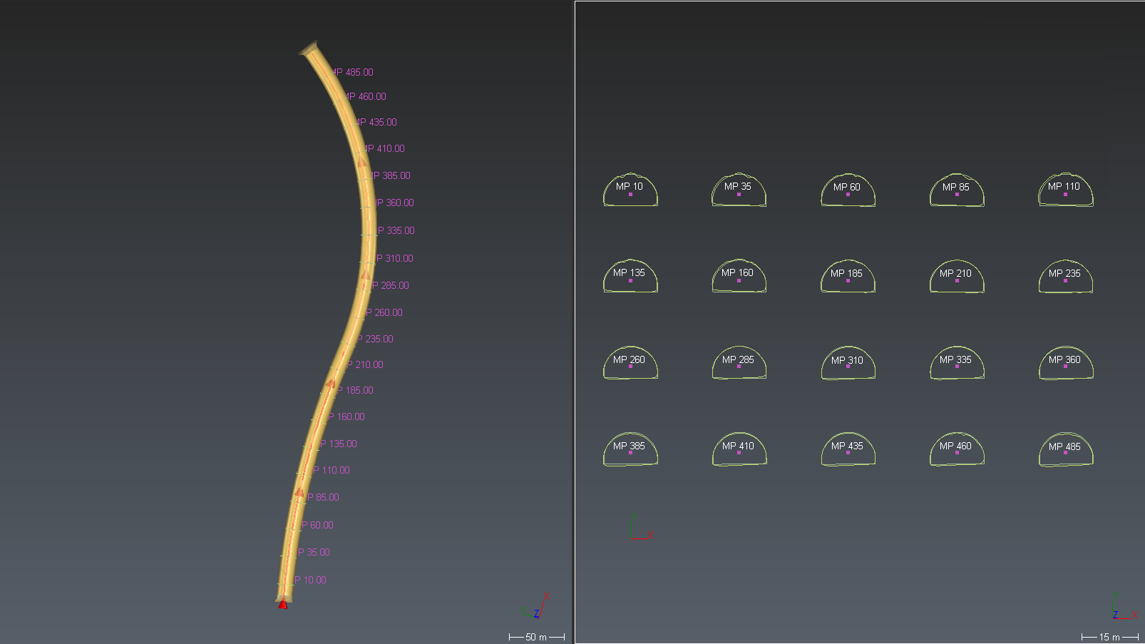 Figure 3: Creating profiles on both meshes, along the neutral axis. 3D and 2D views of the profiles.
Comparing the profiles
We can now compare these profiles in pairs.
If you left the previous command with OK:
Select the new folder called “Cross sections: …”.
Launch the command Compare / Inspect Profiles.
Choose Tunnel (3D inspection).
Choose which profiles will be taken as reference. In this case, it is the profiles from the Theoretical tunnel.
Press Preview to see the result.
Modify the colors of overbreaks and underbreaks.
Press OK to validate and exit the command or 2D Preview / Export to export the results into dxf or to Autocad.
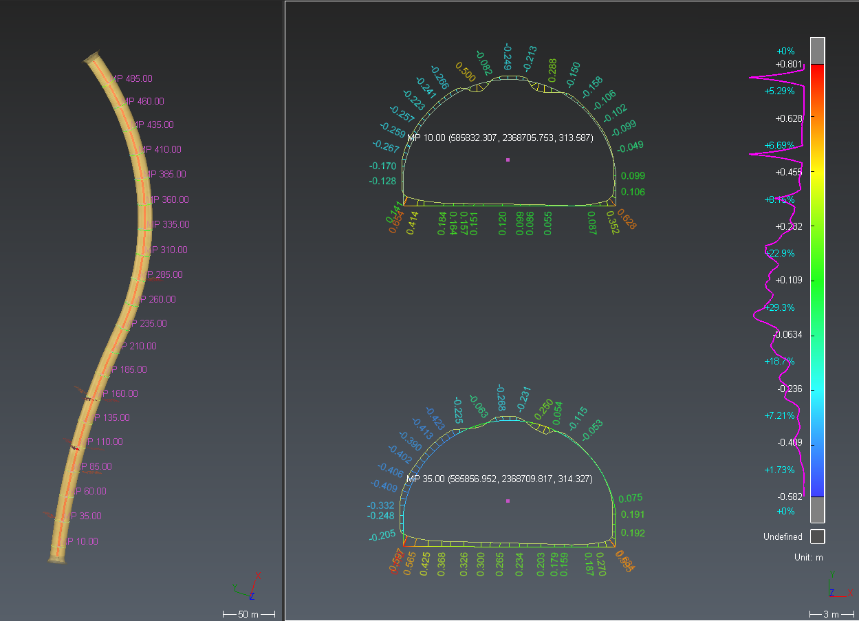
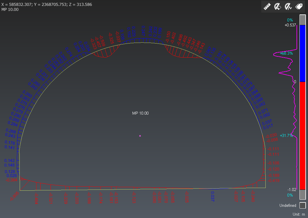 Figure 4: Comparing profiles (example for one couple of profiles).
Computing volumes of overbreaks and underbreaks
Thanks to the profiles that we created, we will now compute, cut and fill volumes of the measured tunnel. The profiles will delimit on which parts of the tunnel the volumes are going to be computed.
Select profiles folder, both meshes of theoretical and measured tunnel, the neutral axis, and launch the command Volume Over/Under.
The first selected mesh will be the reference. Here, you can invert them. Select the Theoretical tunnel as Reference and the Measured tunnel as Measure.
Then, set the computation step (0.25m for instance) and colors for overbreak and underbreak.
Click on Preview.
Colors are put on the tunnel to show zones of overbreak (colored in red by default), and underbreak (colored in blue by default). And one label is associated to each part of the tunnel, showing computed volumes. The total volumes (sum of all parts) are displayed in the dialog box.
Click on OK.
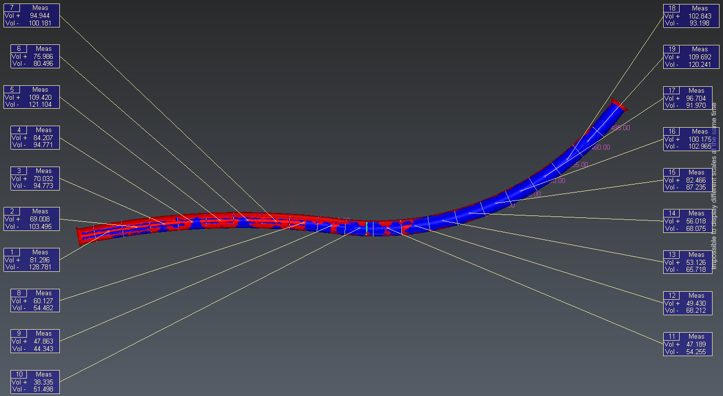 Figure 5: Computing volumes of overbreak and underbreak on parts of a tunnel.
Creating a 2D inspection map
A new colored mesh has been created with this volume computation. We are going to unroll it to create a 2D inspection map of the overbreaks and underbreaks.
Select the colored mesh (Comparison Theoretical tunnel / Measured tunnel in the Volume Over Under group) and select the neutral axis.
Launch the command Unroll around Axis.
Choose the option 2D.
Click on Preview to see the result.
You can display a grid over the map using the bulb.
You can export a picture of the scene by clicking on the Export a picture button.
If you click on OK you will create this 2D map and the grid in the scene.
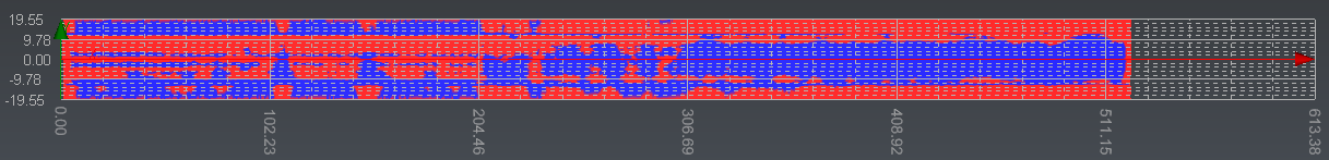 Figure 6: Unroll the mesh of the tunnel to create a 2D inspection map.
Printing the results
Now, three report data objects have been added to the project: one corresponding to the profiles, one to the Volume Over Under and one to the unroll. Open the menu Report. Four chapters have been added to the report: a cover page and one chapter per report data object. These chapters are generated thanks to templates assigned to the report data categories. You may want to customize them:
First, define the global layout. Layout settings are common to all chapters. Choose an A4 Portrait layout with headers and footers Not on first chapter. Reduce also the number of decimals.
Select the cover page and add a title. Use the text toolbar to write it in an appropriate style. You can move the title to the middle of the page by adding some lines. Drag and drop an automatic field (for instance, the date) from the Data panel.
Move the Unroll and Volume Over Under chapters before the Cross sections chapter if necessary (do a drag and drop).
Select the Unroll chapter:
In the header, add a text area containing the chapter title (use the automatic field because the header is common to all chapters).
In the footer, add the page number and the page count.
In the body, select the scene to increase the ratio and to modify the scale. Remove the empty item.
Select the cross sections chapter. Align center the table.
Finally, press To PDF to generate the report in .pdf.
Making a video of a virtual visit
We will now create a virtual visit inside the tunnel:
Go back to the 3D scene
Switch to perspective view (if not already the case).
Show only the neutral axis and all the groups of your profiles.
Select the neutral axis and launch the command Camera Path.
Press X or Y and click on Use Current to set the Z axis as the camera up vector. Check the option Smooth the camera path and set the camera state to Perspective.
Try to play the video.
Place the video cursor at about 12 seconds and press Add / Edit to place a target on a point of a section.
Replay the video from the start.
Record the video as an .avi file.
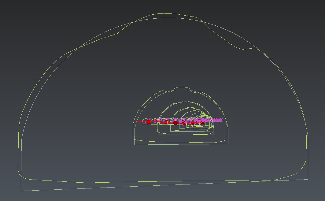 Figure 8: Video of virtual visit.