Point Cloud filtering
Introduction
It is sometimes necessary in a point cloud to split the points, which are not relevant or which can be separately processed in your application, (e.g. monuments and trees on a DTM). In the software, there are several ways of processing the point clouds (bad points removing, point or cloud selecting, etc.)
Manual selection (Clean / Separate)
Automatic selection (Separate on Both Sides, Separate according Distance, Separate according Orientation)
Automatic segmentation or filtering:
Sampling (in the menu Clean \ Cloud Sampling):
Exercise overview
In this exercise, we will see how to split or explode a point cloud in different parts manually or according to a distance parameter. The 3D meshing will be also presented while keeping all points.
The file used in this tutorial is Golf.3dr.
Cleaning or splitting manually the cloud
Select the point cloud.
Launch Clean / Separate.
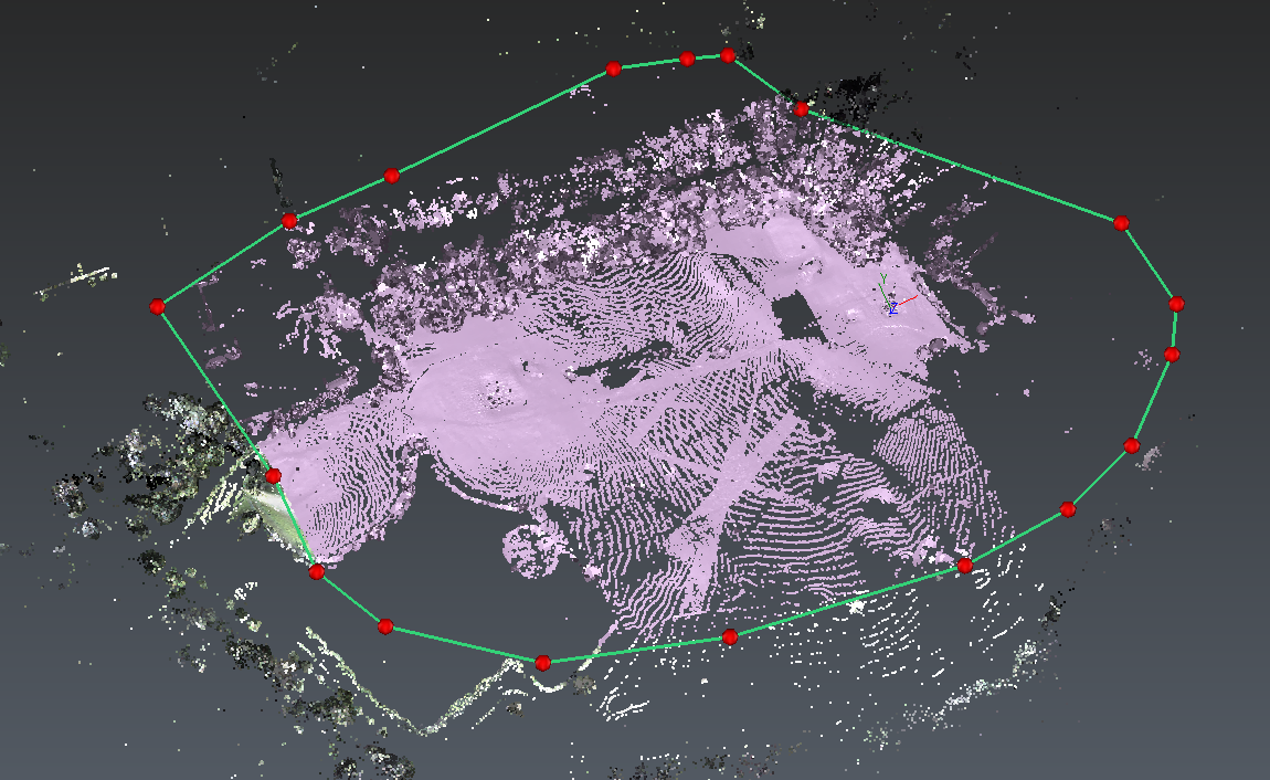 Figure 1: Manually keep the central points
In this command, free, rectangle and circle selection tools take the priority to the navigation. Keep pressing CTRL key or activate the "Pause the current tool" mode in the camera toolbar to pause the selection tools.
Draw a contour, like the one on the picture, to remove the wrong points around the scene. Note that during the contour drawing the view is locked and cannot be rotated.
Press ENTER to validate your contour, which is considered as an extruded contour in the view direction.
You can now rotate again the 3D view.
Choose to Keep the selected points and validate the command.
Coloring the cloud according to a direction
Select the point cloud.
Choose the command Along Direction.
Choose the desired direction, here Z.
Click Preview. Then, click Edit Colors if you want to change the colors or enter precise values as threshold. Several levels can be set to get fixed colors instead of smooth color variations.
Click Ok to validate.
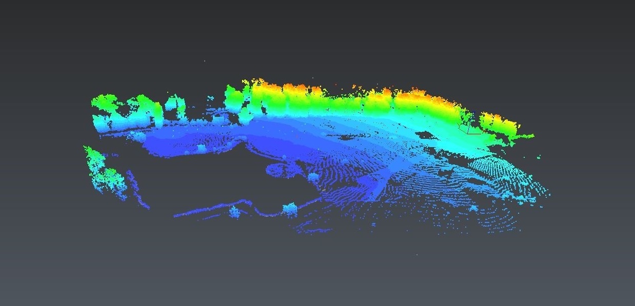 Figure 2: Gradient color along the Z axis
On the Edit Colors command, choose the Over/Under preset, select the red interval and set the bottom peg to 5.5.
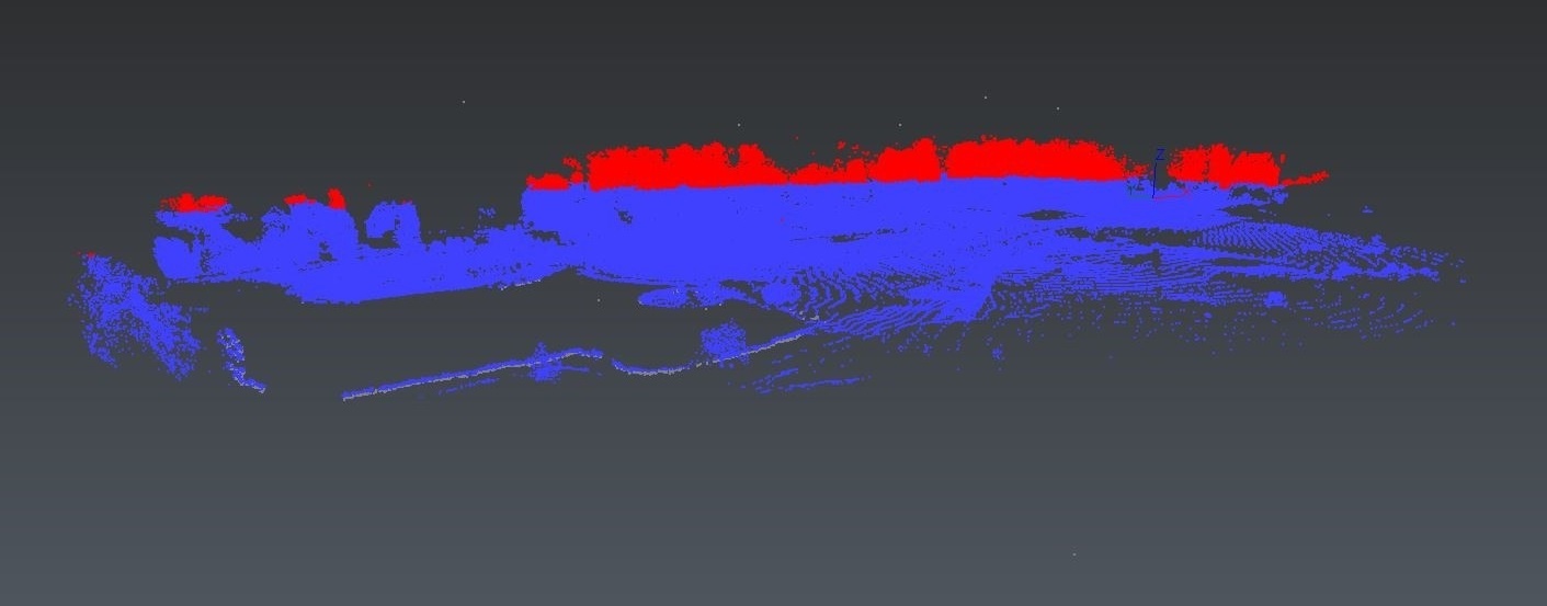 Figure 3: Two levels set in the point cloud
This colored cloud could be used to separate the cloud into 2 parts with the command Inspection Steps. However, in this tutorial, we will use another method to explode it.
Cleaning or splitting automatically the cloud (explode the cloud in small pieces)
Select the point cloud.
Launch Distance.
Enter for instance 0.5m.
This means that the software will try to split the cloud according to a maximum distance between points or a minimum distance between clouds of 0.5 meters.
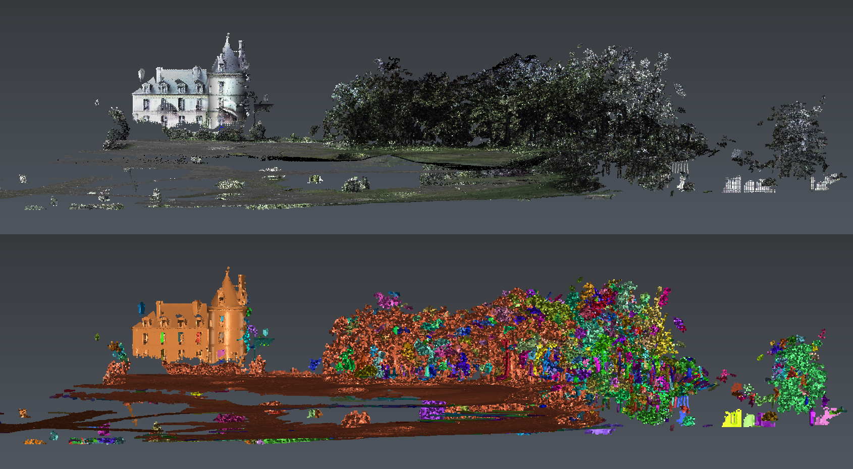
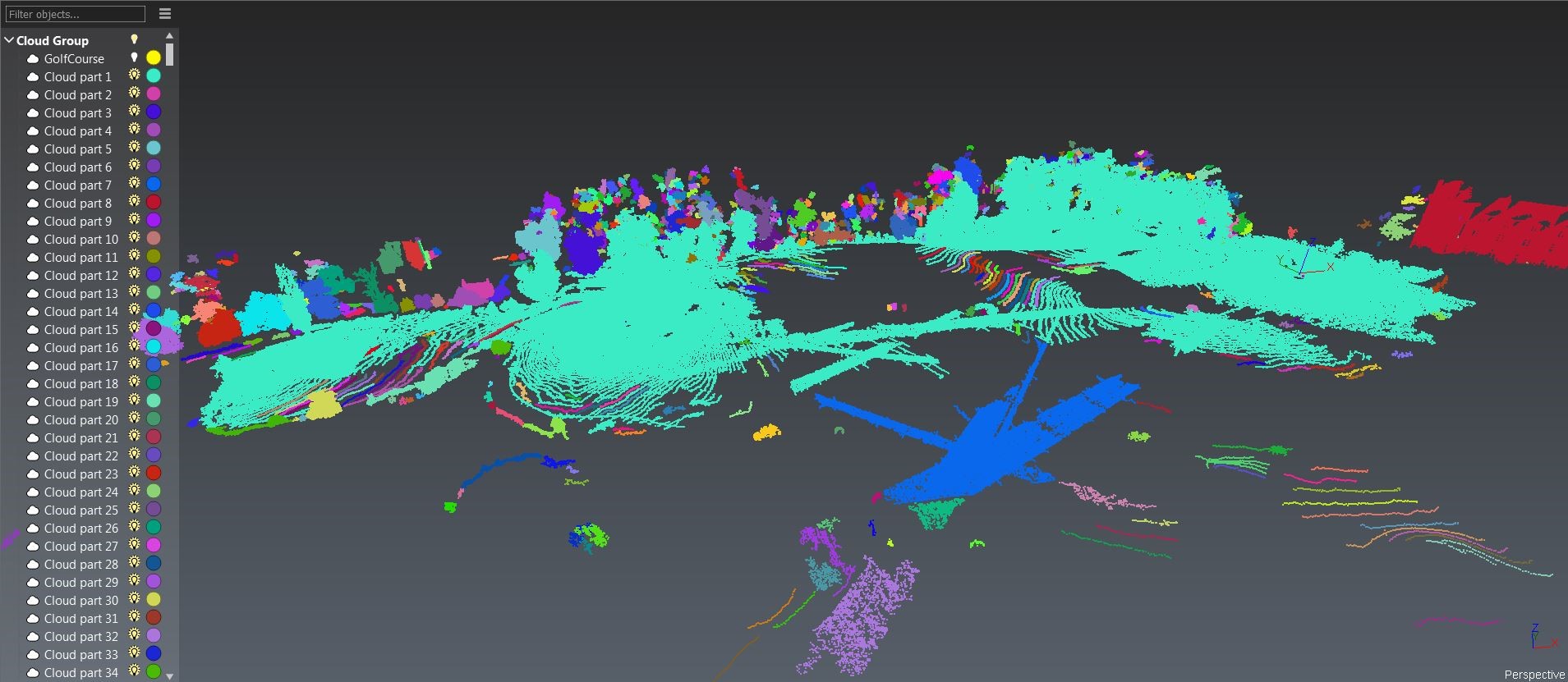 Figure 4: Explode the cloud in smaller pieces according to a distance
This command automatically sorts the sub-clouds by number of points and keeps only the 1000 biggest clouds. You can see all of them in the object explorer sorted from the largest to the smallest in number of points.
Now, you can select the little church which corresponds to the GolfCourse 1 2.
In the graphic scene, use the right click to display only the church (Show only). Or in the tree click on the bulb + Ctrl key to show the object.
Create a 3D Mesh
Select the church (corresponds to the cloud GolfCourse 1 2).
Launch 3D Mesh.
In this command there is an option to mesh all points (only for less than 400 000 points). Meshing all points can be useful to keep all the information from the digitization, only if the cloud does not contain points too noisy or measurement errors. This process can also result in a heavy mesh due to the high number of triangles (see the Meshing Exercise).
The option Try to keep only the external border enables you to automatically fill a certain number of holes.
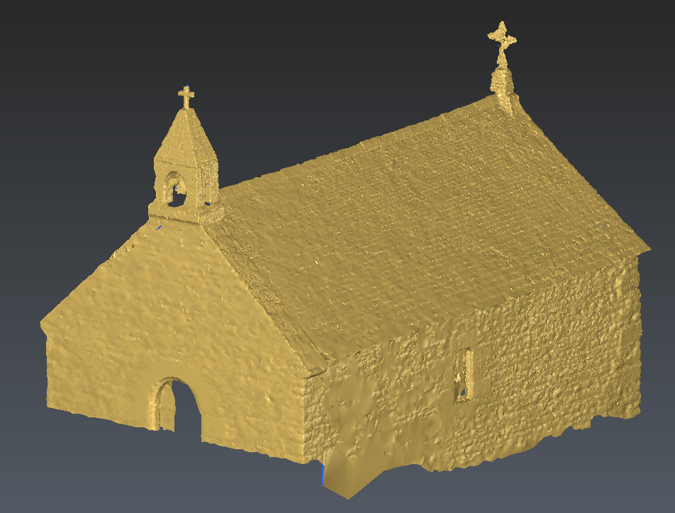 Figure 5: Final 3D model of the church
You can mesh the ground automatically.
First, undo the previous steps with Ctrl + Z in order to have the initial cloud. Then, to extract the ground:
Select the cloud.
Launch DTM.
Choose the following options:
32° for the Max slope
Z as Direction
1m for the Extraction grid size
Check noisy points
Refined and uncheck output clouds
You also can segment the point cloud with this command. Please see the related exercise dedicated to this feature.
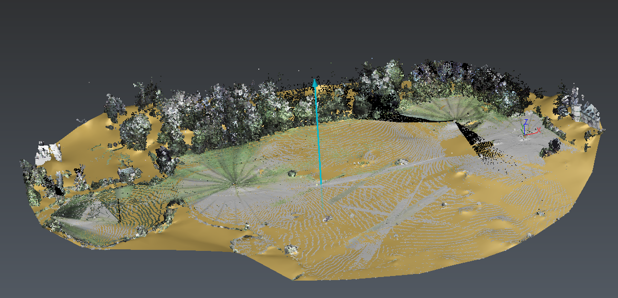 Figure 6: Automatic ground points extraction and 3D meshing
The mesh which has been created by this command can be used to separate the point cloud:
Select the cloud GolfCourse and the mesh previously extracted.
Launch Separate according Distance.
Set a distance threshold of 0.1m.
 Figure 7: Separate the points at a given distance from an object (here a mesh)
It is also possible to automatically separate a cloud according to an object extracted or created beforehand (a polyline, a geometrical shape or a mesh). This possibility is not detailed in this exercise.