Reverse Engineering of a Pelton Wheel - Part Three: Automatic surface creation
Introduction
Reverse engineering is the creation of CAD surfaces from scan data.
In most cases, a scanner provides the point clouds used to create a 3D mesh. Then, CAD surfaces can be computed from the 3D mesh and a polyline network. CAD surfaces can be exported in IGES or STEP format and further used in other software for Computer Aided Manufacturing (CAM), Finite Element Analysis (FEA) or for comparison and inspection.
This exercise is part of full workflow that shows how to convert a point cloud into a CAD model. The steps below give a global description of the full process:
Align the part thanks to the extraction of geometric features on a mesh created from the point cloud
Clean the mesh so that it can be replicated by symmetry and rotation
Create an automatic network of polylines and edit this network in the required areas to create the surface - this is the part covered in this exercise
Exercise overview
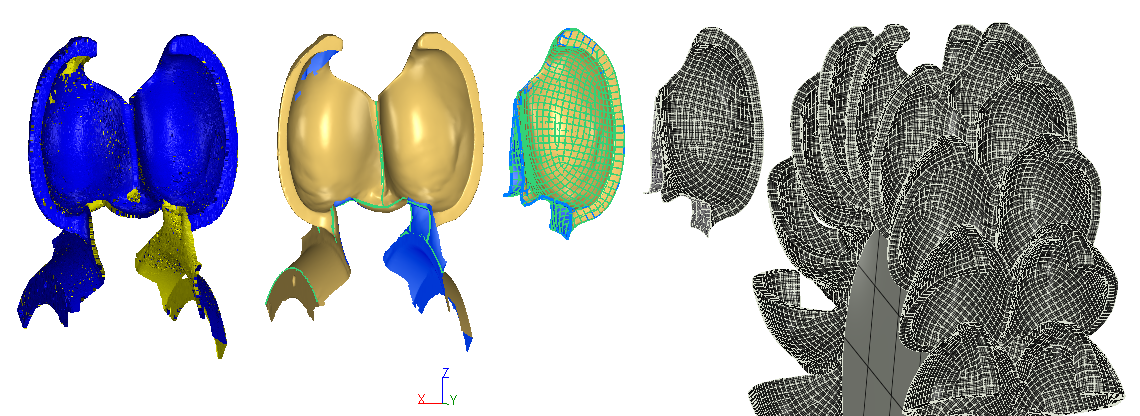
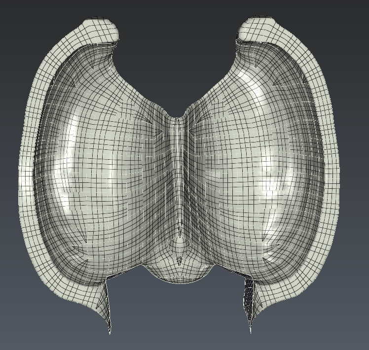
As shown in the figure below, the input mesh of this exercise has been created in a very precise manner so that the borders are exactly planar, circular and front and back fit exactly.
Thanks to this mesh, this exercise will show how to:
Automatically create a network of polylines
Adjust this network in order to fix it or improve it
Create NURBS surfaces from this network
Duplicate the NURBS surfaces to create a solid model
The file used in this tutorial in PeltonWheel_Reverse_3-AutoSurface.3dr
The file can be downloaded on Cyclone 3DR - Downloads page.
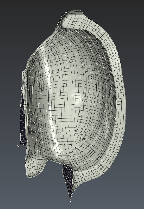
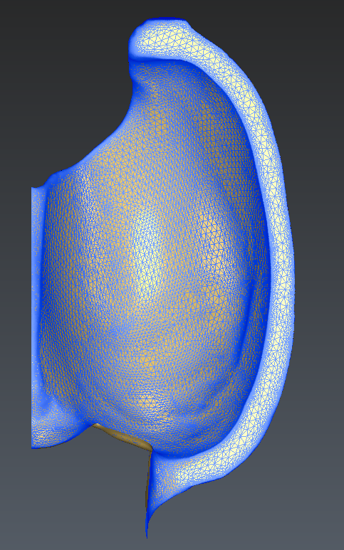 Front view of the input mesh
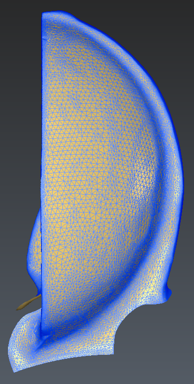 Left view of the input mesh
Automatic creation of the network
Fur such an organic shape, the easiest way to create a network that will later drive the creation of surface patches is to use the tool named Create Network.
Select the mesh and launch this command. There are three options in this command:
The length of the target edge for the network
A border management option
A constraint option (advanced usage, not useful to activate this option in this application)
Border management:
For this mesh, considering that the borders were very precisely created, the right option is Extend to border. This way, the network will be extend precisely to the border.
You can test with the other options to see the differences
Edge length option:
The default value is calculated so that the number of surface patches that would be created remains reasonable.
Enter 10 and see that thousands of tiny patches would be created. This is not what we need here.
Enter 75 and see that the network is nicely created. Only the area of the thin parts need some adjustments.
Hit OK to validate and exit the command
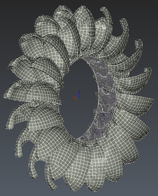
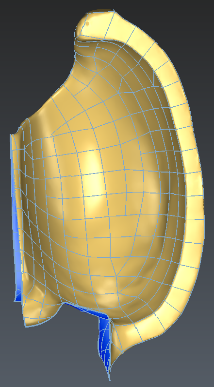 Automatic network created
Adjustment of the network
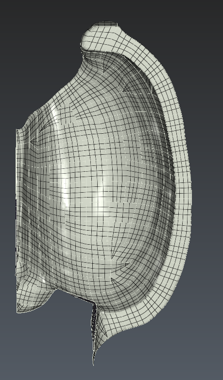
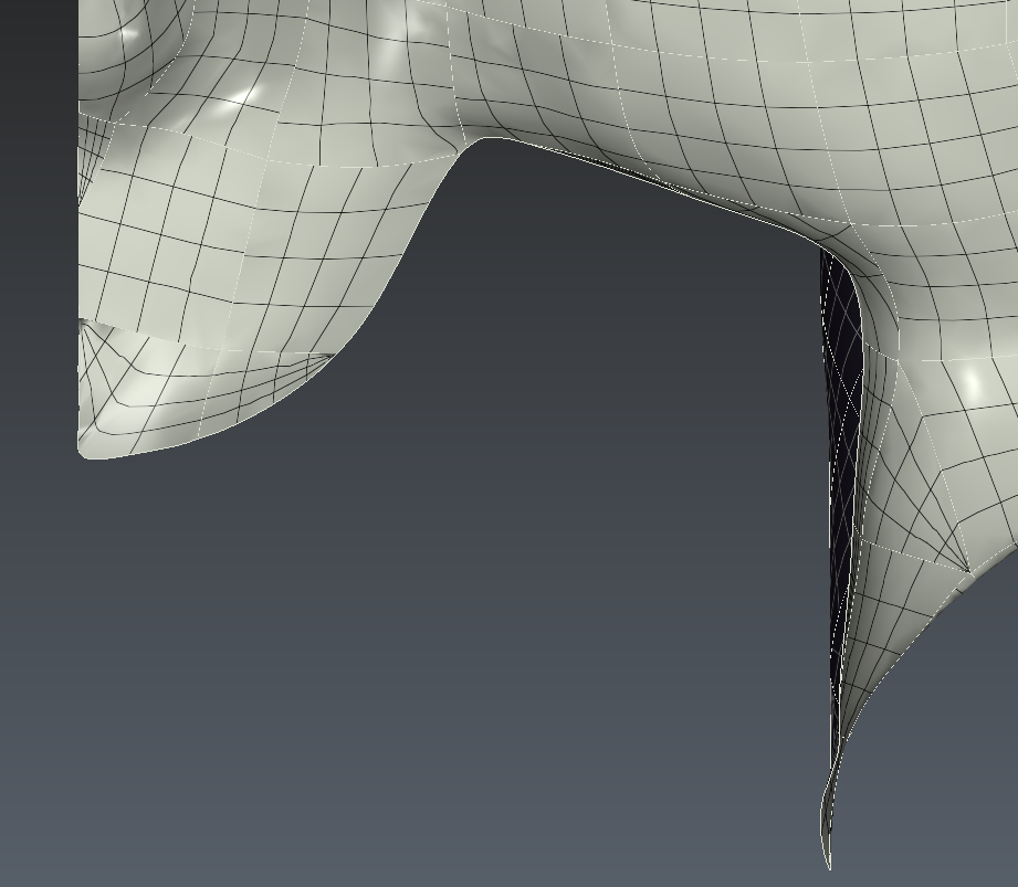
With this network, you can see that the area of the thin parts needs some adjustments.
Actually, the images below show that the network doesn't go until the border.
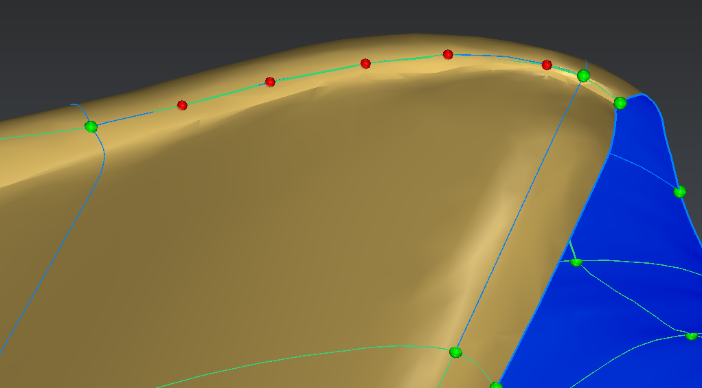
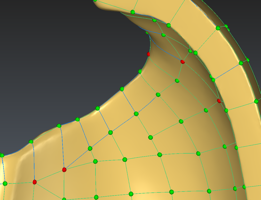
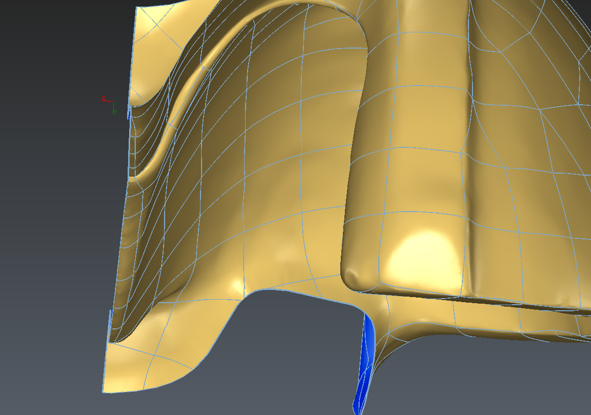 Issue in the created network that needs to be fixed - top view
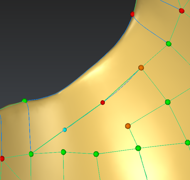
 Issue in the created network that needs to be fixed - zoom
Adjustment on the thin part and close to the border
The first area that needs to be fixed is the one that is close to the border
To do so, select the mesh and the network and launch the command Edit Network:
Select the tool allowing to create new edges (the "+" button)
Pick the green ball
Then press Alt and click a point on the border
In creation mode, the Alt key allows to pick an exact point on the network.
With no key pressed, the point will either be at the extremity of an edge, or at the middle of the edge.
The Alt key therefore allows for more precise control.
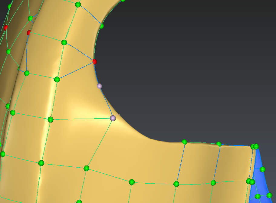
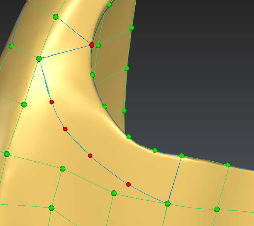
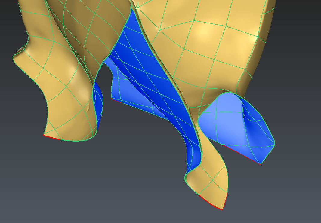
The edge shown in blue in the image below is also not following very precisely the thin area. We will delete it and recreate so that it follows the edge of the part:
Select the tool allowing to modify the network (the pencil button)
Select the edge
Press delete
Select the tool allowing to create new edges (the + button)
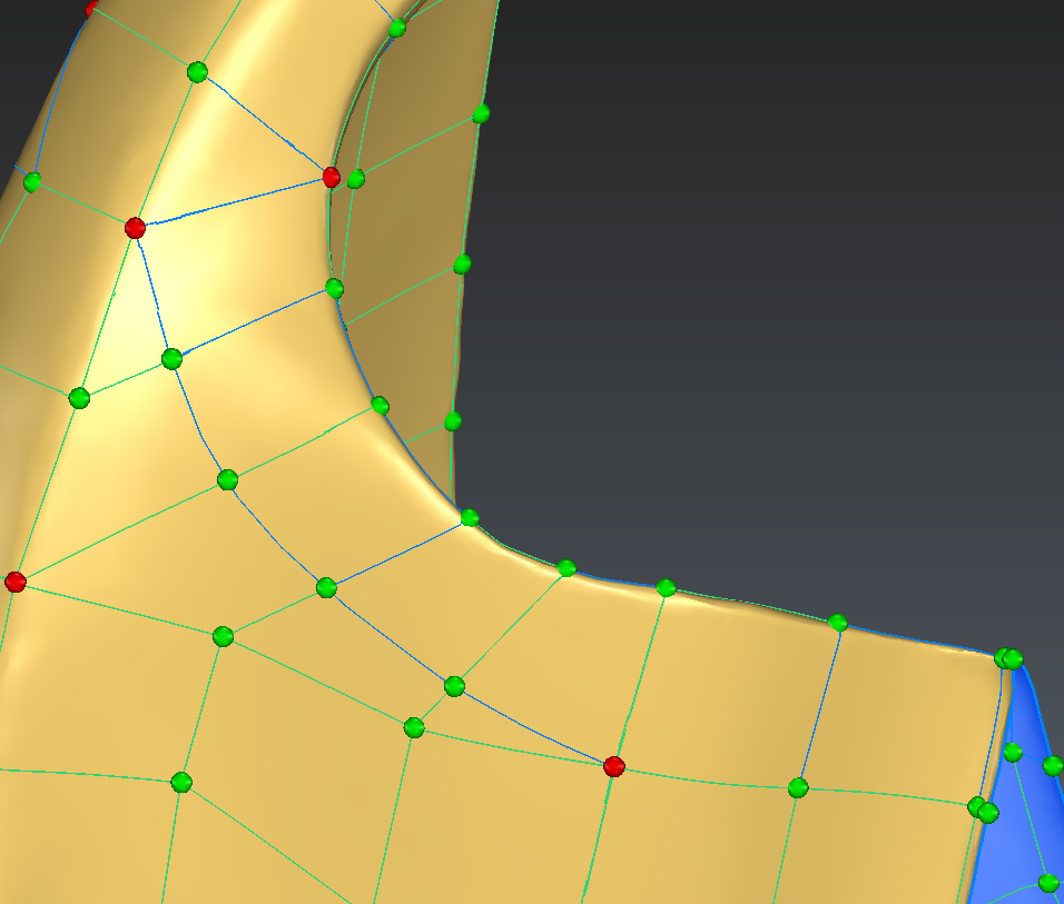
Pick the green ball on the right and then draw the edge so that it reaches the green ball on the right as shown below
Press Enter to validate the edge
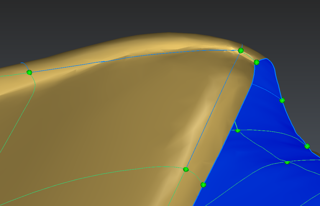 Straight segment replaced with a curved segment - Step 1
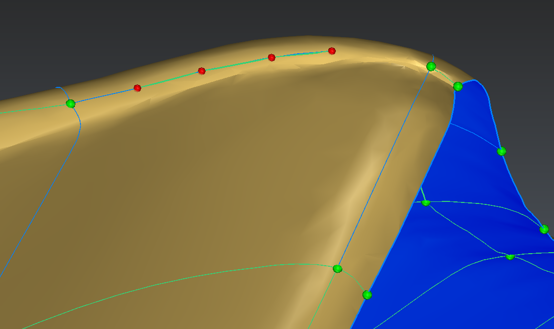 Straight segment replaced with a curved segment - Step 2
 Straight segment replaced with a curved segment - Step 3
Adjustment of the thin part in the middle of the blade
The very same tool will be used to adjust the area which is in the middle of the blade.
Select the mesh and the network and launch the command Edit Network.
The first step here here will be to delete the nodes that will not be used: 2 nodes in the back and 1 node in front as shown in the image below.
Make sure you are in Edit mode. Select these nodes and press Delete on your keyboard.
Use the Ctrl key to select several nodes
 Nodes that need to be selected and deleted - back view
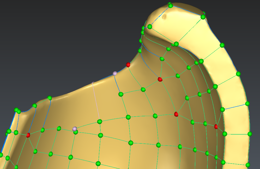 Nodes that need to be selected and deleted - front view
The next step consists in drawing the edge along the thin part. Process just like before:
Select the tool allowing to create new edges (the + button)
Pick the green ball on the top and then draw the edge so that it reaches the green ball on the bottom as shown below
 Drawing a segment along the thin part
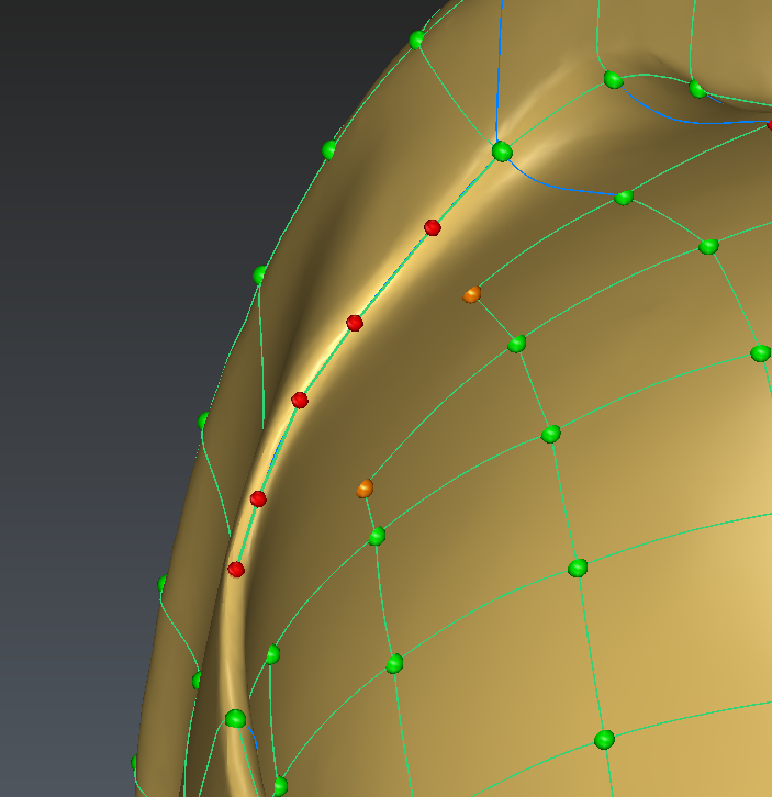
Then repeat the operation on the front of the blade in order to create a line parallel to the thin border as shown below.
 Drawing a segment in the front of the blade
The next step consists in adding edges in order to connect the nodes below and the edge line in the front. Remember to use the Alt key in order to pick a point on the edge line precisely.
 Adding segments to connect the nodes
And repeat the operation on the back:
Draw an edge parallel to the edge line
Connect the nodes below to the ones above (no need to use the Alt key here as the nodes are already created!)
 Same operation repeated on the back of the blade - parallel line
 Same operation repeated on the back of the blade - node connection
Creation of sharp corners in the network
The network is almost ready for creating the NURBS Surfaces.
You can select the network and the mesh and launch the command Generate Patches to look at the result obtained this way.
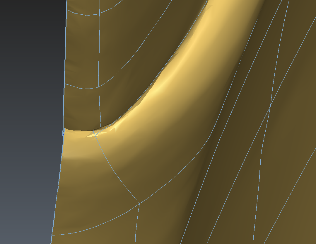
The images below show the results obtained with this network. From far away, the surface is fine: no holes and smooth. When zooming in, you can see that the corners are not sharp.
Keeping these non sharp corners would not allow to create a connected surface for the full blade.
 Default corners are not sharp - front view
 Default corners are not sharp - zoom
In order to create sharp corners:
Select the network of polylines and launch the command Ungroup Polyline
Launch the command Cut Polyline and select the option Vertex / End
Zoom in all 4 corners and pick the exact vertex that need to be cut (do not hesitate to zoom in!)
 Polyline cut in the corners
Creation of NURBS surfaces
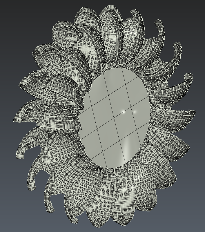
The NURBS surface is now ready for being created: just select all the polylines and the mesh and launch the command Generate Patches.
The surfaces are created automatically!
 CAD shell created thanks to the network
Creation of the full blade
Creating a symmetry
Now that half of the blade is created, it is very easy to create the full blade:
Select the CAD Surface and launch the Symmetry command
Select the option Planar Symmetry
Define the origin (0, 0, 0) as the Axis position
Define X (1, 0, 0) as the Axis direction
Make sure the option to Create copy is activated
At this point, the 2 surfaces are just independent CAD surfaces. There is no link between them.
The link can be created thanks to the command Sew Surfaces:
Select the two CAD surfaces and launch this command
Enter 0 in the Tolerance value (the exact same borders are used on both side of the blade allowing to enter 0 here)
Press preview and see the number of output free contour is 1
Hit OK, Exit to validate the command
 Duplicating the blade by symmetry and sewing
Creating all 18 blades
The next step consists in duplicating the blade so that the full wheel is created.
To do so, copies of the blade have to be created by rotation:
Select the shape
Launch the command Rotation
Define the Axis position as the origin (0, 0, 0)
Define the Axis direction as X (1, 0, 0)
Set the angle to 20°
Check the box to create 17 copies
Validate with OK
In total, this will create 18 blades (the initial one plus the 17 copies)
These 18 CAD shapes are now individual shapes with no connection. The next step consists in sewing them:
Select these 18 blades
Launch Sew Surfaces
Enter a tolerance value of 0.5mm
Hit Preview and validate with OK, Exit
The wires in front and back of the blade are not exactly mathematically the same because the network that was used did not consider any constraints in the front and back of the blade.
For this reason, a value of 0.5mm is necessary here.
Note that the number of output free contours is 2 here: on each side of the wheel
 Duplicating the blade by rotation and sewing
Creating a solid model
The CAD model created at previous step is almost a solid: only 2 holes remain to be filled. This final step consists in filling them:
Select the CAD shape and launch the command From CAD Surface
The 2 external wires are extracted
Select the first wire, launch the command Fill Surface and press OK
Repeat the operation with the second wire
These operations created 2 surfaces restricted by the input wires.
In order to create a solid:
Select the 2 planar surfaces and the CAD surface of the 18 blades
Launch the command Sew Surfaces
Enter 0 in the tolerance
Hit OK to validate the result
The shape is now a solid model of a pelton wheel.
 Final solid model of a Pelton wheel
This CAD solid model can now be exported to STEP file for further processing:
Being machined by a CAM software
Or being analyzed in a CAE software package