Reverse Engineering of a Pelton Wheel - Part Two: Mesh Improvement
Introduction
Reverse engineering is the creation of CAD surfaces from scan data.
In most cases, a scanner provides the point clouds used to create a 3D mesh. Then, CAD surfaces can be computed from the 3D mesh and a polyline network. CAD surfaces can be exported in IGES or STEP format and further used in other software for Computer Aided Manufacturing (CAM), Finite Element Analysis (FEA) or for comparison and inspection.
This exercise is part of full workflow that shows how to convert a point cloud into a CAD model. The steps below give a global description of the full process:
Align the part thanks to the extraction of geometric features on a mesh created from the point cloud
Clean the mesh so that it can be replicated by symmetry and rotation - this is the part covered in this exercise
Create an automatic network of polylines and edit this network in the required areas to create the surface
Exercise overview
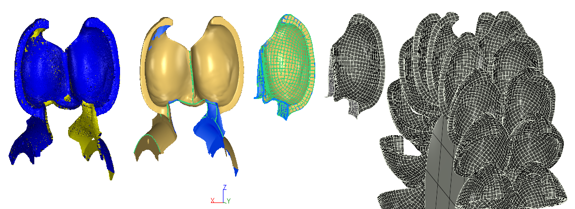
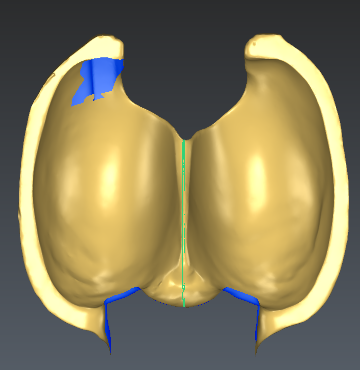
As shown in the figure below, the mesh created during the part I is correctly aligned but requires further cleaning before creating NURBS surfaces.
The following cleaning operation steps are required:
Creating a bridge
Filling holes with curvature
Defining a clean planar and circular border on the bottom
Defining a clean border on the back of the blade
Replicating the back border on the front of the blade
Sectioning the mesh with the symmetry plane
The file used in this tutorial in PeltonWheel_Reverse_2-MeshImprovement.3dr
The file can be downloaded on Cyclone 3DR - Downloads page.
Creating a bridge
Because of its complex shape, the hole which is in front of the blade is difficult to fill automatically. You can try filling the hole with different curvature options and see that the result is not correct.
To fill this hole any how, an initial step consisting in creating a bridge is necessary.
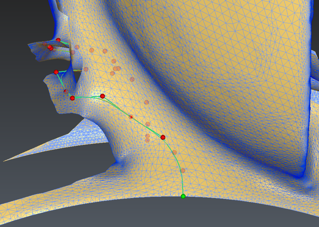
Launch the Bridge command and pick 2 edges of this hole: one on the top of the hole and another one at the bottom of the hole like in the picture below.
Regarding the parameters:
The default orientation and tension value are fine
Uncheck the Planar axis option as it is not mandatory in this case
Check the Sew option to obtain a single mesh after this process
Hit OK, Exit to validate the result.
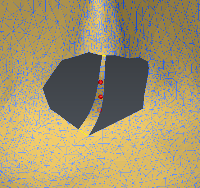 Creation of a bridge in the middle of the hole
Filling holes
In this tutorial, we will create a CAD solid model of a pelton wheel based on half of one blade, it is therefore necessary to fill the holes only on the right side, which is less damaged and has less holes than the left side.
Select the mesh and launch the command Fill Holes.
There are only 3 holes on the right side of the mesh: the 2 in front (with the bridge in the middle) and the one in the back.
You can pick these holes with your mouse or using the option to Select borders shorter than 400 mm.
Make sure that the option to fill with Curvature Filling is checked.
Validate with OK, Exit
In some conditions, holes can be filled without additional steps with the right curvature.
In some other conditions, it will be necessary to help the algorithm by adding a bridge in the middle of the hole in order to improve the results and better follow the curvatures.
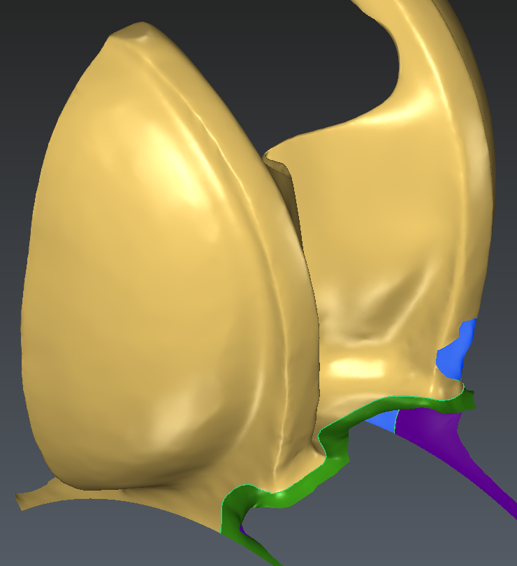
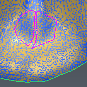 Hole filled thanks to the bridge created previously
Defining a clean planar and circular border on the bottom
In this tutorial, we will focus on the blade itself and not how it is fixed onto it axis. As a result, we will cut the lower part of the mesh so that it follows a clean planar and circular circle.
This requires the following steps:
Creating the right cylinder
Creating the intersection between the mesh and the cylinder
Cutting the mesh with this intersection polyline
Projecting the polyline onto a vertical plane
Re-meshing the border of the mesh so that it follows the projected polyline
Creating a cylinder
Launch the command Draw Cylinder, lock all the 4 parameters and set them to the following values:
Center -500, 0, 0
Axis = 1, 0, 0
Radius = 1 m
Height = 1 m
This will create a cylinder of 1 m radius and 1 m height along the rotation axis of the blade (X).
Creating the intersection between the mesh and the cylinder
Select the cylinder and the mesh and launch the Intersection command. Validate with OK, Exit.
Because the cylinder intersects the mesh at different areas, the output is a set of polyline.
You can now hide the cylinder.
Cutting the mesh with this intersection polyline
Select the set of polyline and the mesh and launch the Cut Mesh command.
In the options, do not close or project the polyline. And validate with OK.
You can hide or delete the 4 meshes which are not relevant here and keep only the main part.
 Result of the cut operation: 5 different meshes
Projecting the polyline onto a vertical plane
Because the intersection between the mesh and the polyline is not a planar circle, we need to work a little more on this part of the mesh.
The area we want to focus on here is only the right side of the blade: out of the 4 independent parts of the set of polyline from the intersection, only one (the biggest one on the right) is interesting.
Select the set of polyline and launch the Ungroup Polyline command and delete the three parts which are not relevant.
We will now project this polyline onto its best plane perpendicular to the rotation axis:
Select the polyline
Launch the Best Plane command
Define the normal direction as X
In the dialog, you can make sure that only the plane is created as an output
Hit OK
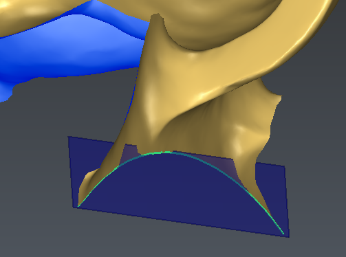 Best plane perpendicular to the rotation axis
Now that the plane is created, it is only necessary to project the input polyline onto the plane:
Select the polyline and the plane
Launch the Projection command
Make sure that the projection option is Shortest distance
Hit Preview and validate by OK, Exit
The projected multiline and the input ones are very close to each other as the intersection was almost planar. Zoom in to look at the difference.
You can hide the plane and the input polyline to show only the mesh and the projected (and therefore planar) polyline.
Re-meshing the border of the mesh so that it follows the projected polyline
This step will modify the border of the mesh on the side of the Pelton wheel so that it follows exactly the planar polyline:
Select the mesh and the planar polyline
Launch the Define Borders command
Enter a cleaning distance of 30 mm
Hit OK to validate the result
You can hide the polyline for the next steps.
 Clean planar and circular border on the side of the mesh
Defining a clean border on the back of the blade
The objective of this step is to modify the back of the blade so that it is a clean border that can be replicated in the next step in front of the blade.
To do so, a smooth projected polyline will be created:
Select the mesh and launch the Projected Polyline command
Then click from the right of the blade to the left in order to create a smooth polyline
At any point, you can drag an existing control point to adjust locally the created section
In order to make sure that the polyline drawn reaches the border of the mesh, drag the extremity control point towards the mesh border. It is actually not possible to click exactly on the mesh border but moving the extremity of the polyline to the mesh border is possible.
You can deselect the CAD curve output and keep only the projected polyline
Validate with OK, Exit
Try to make the polyline as symmetrical as you can, especially in the middle of the blade
Try to make the polyline extremities as perpendicular as you can to the mesh border
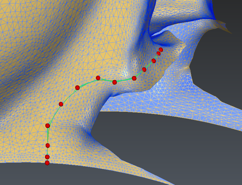 Creation of a smooth polyline on the back of the blade - Step 1
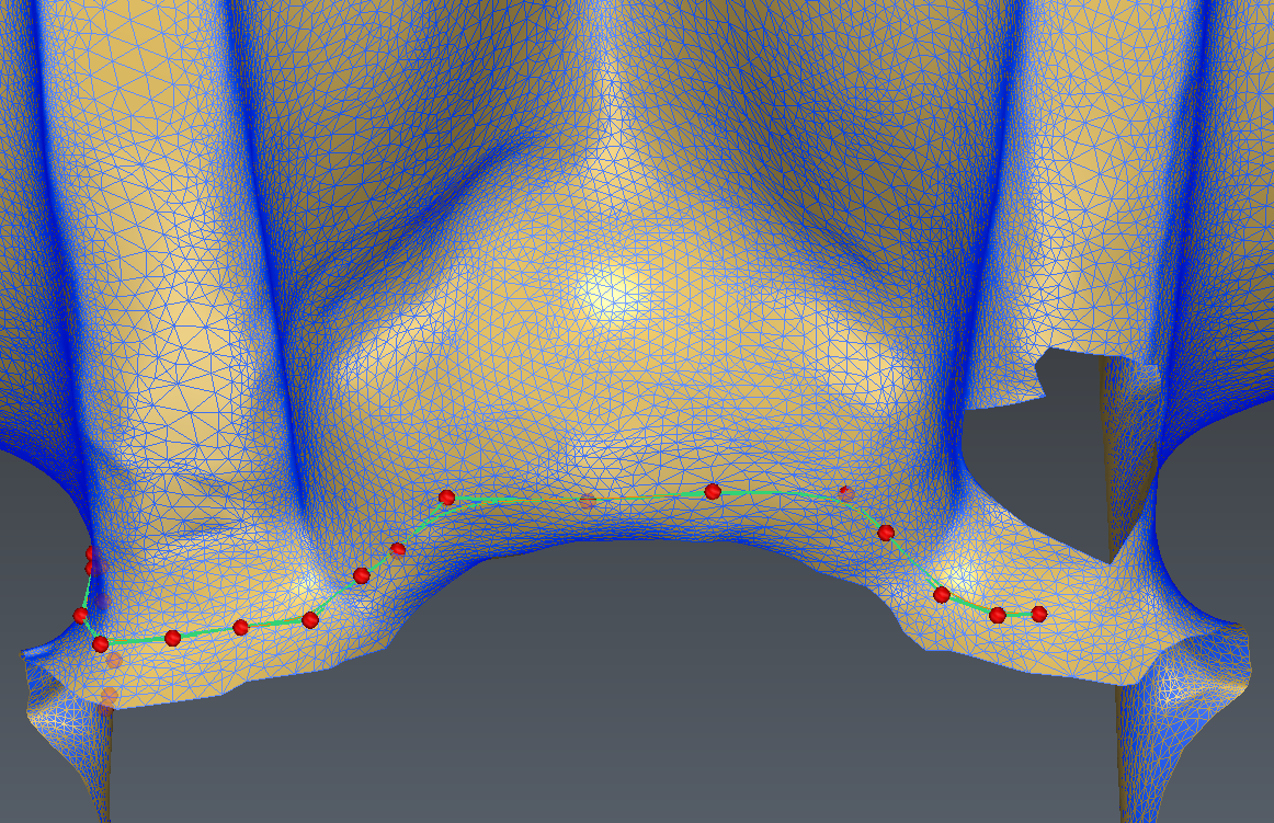 Creation of a smooth polyline on the back of the blade - Step 2
 Creation of a smooth polyline on the back of the blade - Step 3
Now that the polyline in the back of the blade was created, you can cut the mesh:
Select the polyline and the mesh
Launch the Cut Mesh command
Do not close or project the polyline
Validate with OK
You can delete the small part and keep only the main one.
If the mesh is not split in 2 parts, this is because the polylines extremities do not reach the mesh boundaries.
You can use the command Stretch Polyline to fix that. In this case, make sure that the polyline is projected onto the mesh (select the mesh as well before launching the command).
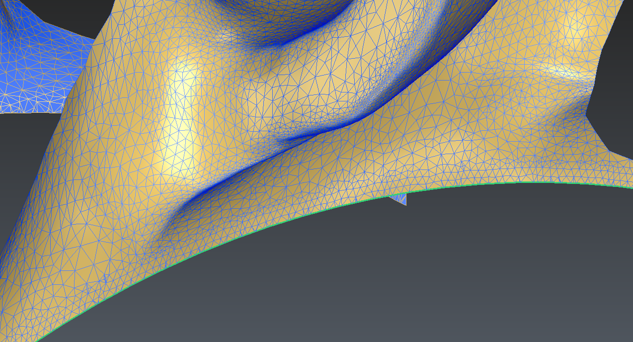
 Meshed with a clean border on the back
Replicating the back border on the front of the blade
In order to create a mesh which front side of the blade connects perfectly with the back side of the blade, we will replicate the back border on the front of the mesh:
Select the polyline in the back of the blade (the one that was used to cut the back)
Launch the Rotation command
Define the Axis position as 0, 0, 0
Define the Axis orientation as 1, 0, 0
Define an Angle of -20°
Check the Create copies option and ask for 1 copy
The next step here is to define this rotated polyline as the front border of the mesh:
Select the rotated polyline and the mesh
Launch the DefineBordersC command
Define a cleaning distance of 30 mm
Check the side of the mesh that will be cleaned-up (see Tip below)
Hit OK
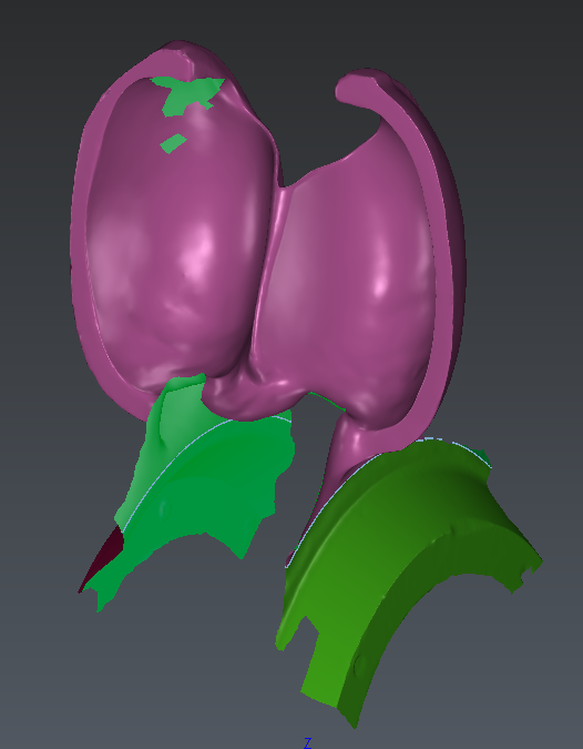
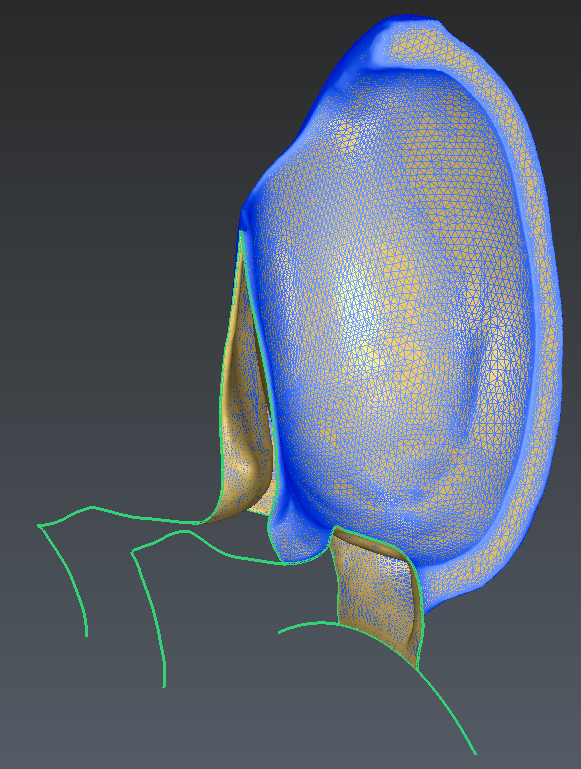
You can see in the image below that the blue section shows where the mesh is cleaned-up. In the image on the left, the blue polyline is defined on the right side. The Define Borders command can be applied straight away.
Depending on the curve drawn on the back of the blade, it might happen that the algorithm picks the wrong side of the mesh to clean (image on the right). In this case, it is necessary to manually delete some triangles in front of the blade with the command Clean / Separate Mesh.
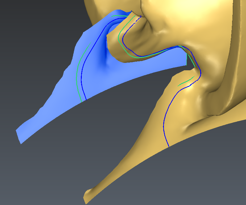 Cleaning distance applied in front of the blade - the corrected area is created on the right side
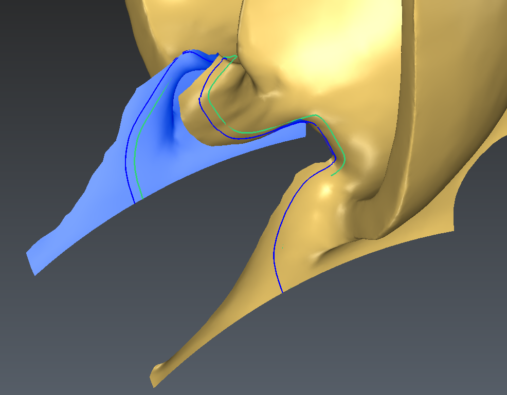 Cleaning distance applied in front of the blade - the corrected area is created in the wrong side
The output of the command is a mesh which now has a clean border but is also made of additional parts. To get rid of these, ungroup the mesh and delete the small parts.
You can hide the polyline in front of the blade.
In order to make sure that the front and back of the mesh match exactly, you can create a copy of the blade by rotating it -20° along the X axis.
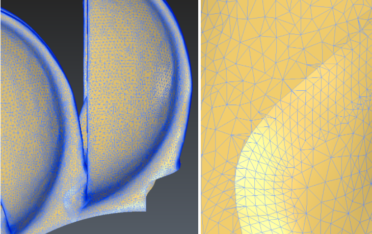
The exact connection between the back and the front should be visible in Flat + Wire representation.
Sectioning the mesh with the symmetry plane
In this exercise, the final operation consists in sectioning the mesh with the symmetry plane:
Select the mesh and launch the Planar Sections command
Define the Axis as 1, 0, 0
Select the option List of distances and enter one value: 0 as you want to section the mesh along the plane on X=0
Uncheck the Output option to get the planes
Validate with OK
 Create one section in the middle, perpendicular to the X axis
The polyline created with this command allows us to cut the mesh exactly on this border:
Select the mesh and the polyline
Launch the Cut Mesh command
Hit OK
The output of this command is 2 meshes. Only the one on the right is interesting and you can therefore delete the other one.
 Final mesh with clean borders