Roundness
![]()
This command allows you to check the roundness of a tank at different heights. This command creates:
cross sections on the best cylinder
cross sections on the mesh of the tank
inspections between these cross sections
Requirements
The mesh of the tank defined for the project is used by default. However, it is possible to create sections on any other mesh by selecting it before launching the command. You can, for example, use only the shell of the tank after using the command Separate Shell. The Best Cylinder must be computed before launching this command.
Choose the Direction of the axis to use to compute sections. It is possible to use:
the direction of the best cylinder: to create sections perpendicular to this axis
the Z direction: to create horizontal sections (according to the current CS).
Define the Radii Tolerance or use the tolerances defined by the API 653. When using API 653, two tolerances are used: one for sections lower than 1ft above the reference height and one for sections higher than 1ft above the reference height.
Choose which point defines the height 0. Read the note below Altitude vs Elevation.
Use the elevation marker defined at the beginning of the project (CreateEditProject).
Use the lowest point of the tank in the chosen Direction.
Choose where to create your sections from the height 0:
with a regular step between each cross section: all over the mesh or on a certain part,
by giving a list of heights,
by clicking points on the mesh where sections need to be created.
Click Preview to compute the sections and check the results. The sections will be previewed in a 2D layout, so that the results can be easily checked. The option 3D allows to split the view vertically, in order to visualize the 3D elements in the left view and the 2D layout in the right view.
You can edit the colors of the inspection by clicking on the Edit Colors button.
Notes
In the case of horizontal sections, the reference cylinder will be considered vertical.
Tips & Tricks
In the report editor, it is possible to view and export as CSV the roundness values for each point of each section. The values are stored so that the first point of each section is located near the orientation marker, and values follow each other in clockwise direction.
Technical information
Altitude vs Elevation
Keep in mind that altitude and elevation are not the same concept:
altitude refers to the sea level. In the software, the origin point is the origin of the active coordinate system.
elevation refers to the local height. At the beginning of the tank inspection, you compute the best cylinder of your tank and you define two markers (elevation and orientation). That is why, you do not need to define a UCS for each tank. You can, also, work in whatever coordinate system you want.
Thus, each section can be defined by:
its height (elevation) along the tank axis
the coordinates of its intersection with the tank axis (X, Y, Altitude)
The values of altitude and elevation are identical if the tank axis is vertical and if the origin of the active UCS is at the bottom of the tank. So as to draw sections on true altitudes: you have to define the elevation marker on (0, 0, 0) and choose the option Perpendicular to Z axis (horizontal sections), unless you have forced the best cylinder to be vertical.
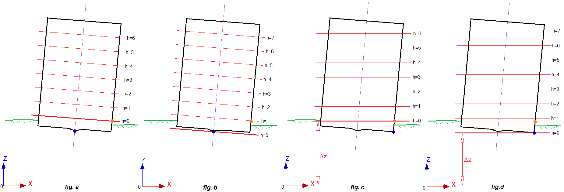
fig. a: Perpendicular to the best cylinder axis+Elevation marker
fig. b: Perpendicular to the best cylinder axis+The lowest point
fig. c: Perpendicular to the Z-axis+Elevation marker
fig. d: Perpendicular to the Z-axis+The lowest point