Rules to make a good polyline network
Our Reverse-engineering process is based on a polyline network that you must achieve first; so, before having your CAD objects (curves and surfaces), you must create delimitations with polylines on the mesh.
This process can be manual or automatic.
Automatic or quick network extraction
You can use the command Create Network which creates a grid network of polylines on the selected mesh(es).
This grid can be edited via Edit Network in order to improve the delineation locally (select the mesh and the network).
Generate the CAD surfaces from a mesh and the polyline network Generate Patches. Select the mesh and a polyline network.
Manual network
To make a manual delimitation you must follow these rules as much as you can:
Make borders on zones having same curvature characteristics: lines along a small radius, lines along sharp edges, etc.
Create polylines that intersect so that the software can easily determine the accurate intersection. To do so, you can use all available polyline creation tools (freehand sections, planar sections, single break line, etc.), and all polyline editing tools (in particular Edit Network or Stretch Polyline command).
The lines that are created must lie “on” the mesh (projected); otherwise some surface reconstruction may fail.
Make contours with 4 sides (wherever possible).
Make smooth polylines along curvature discontinuity
The goal of the surface reconstruction is to divide the complete surface of the model into elementary surfaces called “patch” or “face”. The most interesting property of the NURBS / BSpline mathematical definition is that the surface is continuous. “Continuous” means that the shape changes smoothly from a point to another point of the same face.
Some discontinuities may exist in a surface but they are always located on the border between two patches. This never occurs inside one patch. You may have two types of discontinuity:
Tangency discontinuity: typically this occurs when you have a sharp edge on your model.
Curvature discontinuity: typically this occurs when you have a fillet on your model.
When you create your polylines network you must follow the discontinuities on the surface as shown on the figure below.
When you have a fillet, it is important to consider that there is one curvature discontinuity on each side. This means that you should have 2 curves: one on each side on the fillet like on the right picture and not only one on the top of the fillet, as shown in the picture on the left. These lines can be extracted with Single Breaking Line.
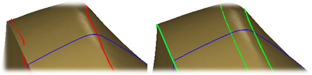 Polylines along curvature discontinuity; lines should be as on the right, they are smooth and correctly positioned on the discontinuities.
Make polylines intersecting each other
You must have intersecting lines in order to create a real network. From a network of intersecting lines, the software will automatically calculate the intersections and trim irrelevant parts. Every time a valid polyline contour is detected, the software will automatically transform polyline pieces into NURBS curves and fill a surface patch inside the contour.
Make contours with 4 borders
The mathematical definition of a NURBS surface has exactly 4 borders. Then, it is better to make as much as possible rectangular contours with 4 borders when designing patches.
When the software analyzes the borders, several situations may occur:
|
Border with 4 sides |
This is the ideal situation. |
|
Border with less than 4 sides |
The algorithm will create a degenerated face, which means that the mathematical definition will keep 4 borders but some border(s) will have a null length. |
|
Border with more than 4 sides |
The algorithm will create a trimmed face from the input contour. |