Generate patch on a mesh
The main command to create surface patches is Generate Patches. This command is very powerful because it drives you directly from a set of polylines to the set of patches.
You can launch the command by selecting a network (polylines, set of polylines, BSpline, etc.) and a mesh.
Open the file Reverse-MetalSection.3dr.
This file contains a mesh and some polylines created with the following commands:
Select the mesh and all the polylines from the folder Contour group, then launch Generate Patches. At startup, the command will automatically process a set of operations to give a first result:
Lines of the network are approximated by BSpline curves with an automatic tolerance (by default the software tries to find the best compromise between accuracy and smoothness).
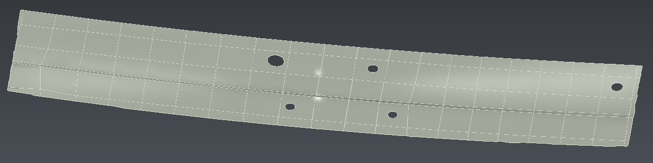
Patches are created from the curve network and fitted on the mesh. Hide the input mesh.
Each time the computation has finished, information regarding the standard and maximum error deviations will be outputted to give an idea about the overall accuracy of the CAD model:
Deviation between the input lines and the corresponding CAD curves
Deviation between the mesh and CAD faces
If you want to locally adjust curve approximations, you can select a single curve and edit the slider value (deviation values change in the dialog box). The new curve will be automatically recomputed and displayed in the 3D scene. Then the next computation will only occur on CAD faces whose borders have been modified.
Feel free to reproduce the network using the commands listed above.
When some patches are missing, it is possible to reconstruct them individually using a CAD wire and Fill Surface.
Sometimes it is interesting to make holes directly on the patches: this is useful if you want a smaller number of patches or if you want to avoid tangency problem between surfaces. To do this, the best way is to have a patch larger than the hole.
Extract the mesh holes with the command Click Holes and Borders to get a polyline around each hole.
Select the corresponding polylines and launch the command From Polyline to transform them into NURBS curves. Choose Auto mode.
Ungroup the CAD surface using Ungroup CAD in order to select the patches individually.
Select each patch and its hole and launch Hole. In a similar way you could change the patch external contour using Surface Restriction.
If necessary, reverse the patch using I shortcut key.
Finally, select the visible patches and create a shell with Group CAD
 CAD result
When you have reconstructed your CAD curves and surfaces, you may want to use them with other CAD-CAM software. Select objects that must be exported and go to the Export and choose IGES or STEP format.