Simulate
![]()
This command allows you to simulate a scan by uploading a .nsd of a previous scan.
Requirements
No selection is required to launch the command.
To create the .nsd file required for the simulation, do a scan with the command Measure through RDS and then export the cloud as a .nsd file through the command File > Export > Export Selected Cloud(s).
Simulator
Click on the button
 to open the file explorer.
Choose a .nsd file of a previous scan.
Set the frequency.
Launch the simulation
 .
.You can pause the simulation using the button
 .
.
Scan mode
User can choose between three default scanning modes and a custom one:
![]() Slow and detailed: settings to obtain a scan with details. This settings requires to scan quite slowly, or you will have some missing parts in your scan.
Slow and detailed: settings to obtain a scan with details. This settings requires to scan quite slowly, or you will have some missing parts in your scan.
![]() Intermediate: compromise between details and speed.
Intermediate: compromise between details and speed.
![]() Fast and smoothed: settings to obtain a smoothed scan. Detailled areas will not be correctly scanned but you can scan fast and avoid holes.
Fast and smoothed: settings to obtain a smoothed scan. Detailled areas will not be correctly scanned but you can scan fast and avoid holes.
![]() Custom: your latest custom parameters.
Custom: your latest custom parameters.
The 3 defined modes set automatic values for all filter options. You can hide or show these values using the arrow button.
To use specific values, choose the custom mode. Each time you edit a parameter, it will be saved in the custom mode.
Outputs
You can choose to create a mesh, or not.
You have 2 parameters to manage the mesh you create:
Grid size: the size of the triangles in the final mesh
Hole size: the maximum size of holes that will be filled when creating the mesh
You can choose to keep only triangles that are in the grid plane.
Scan options
Filter stripe is an option used to reduce the number of points on straight section. Actually, a stripe is a set of points that can be linked to get a polyline. The stripe filtering reduces the number of points in this polyline by creating a few segments. On areas where the distance between the real data and an ideal segment is below Max deviation, the measured points are removed. When the distance is higher, a new segment is created. The final polyline is resampled to respect the criterion Max point spacing between vertices.
Filter according to scanning direction allows you to filter points in order to keep only the best measured points. Once the scanning is done, the normal of each point of the cloud is computed. If the angle between the scanning direction and the normal is higher than the defined Angle, the point is automatically removed.
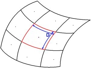
Sampling density is used to activate the real time filtering and provides a good way to obtain a cloud with a uniform point density, independent of the measurement speed. The Sampling density value is the size D of a square grid, which is projected on the shape during the measurement. During the measurement process, the software will keep only 1 point in each grid cell (If more than 1 point, the software will automatically select the best point).
Cutting plane
This section allows you to define a plane below which points will not be measured. Useful to not measure points on a table or on the floor for example.
Select the option Filter points with a plane to enable the option. There are three ways to define the plane:
Select an existing plane in the scene with Select in scene. The command is disabled until the user has clicked a plane or has not left with Esc.
Define a plane with its center and a direction.
Probe a plane with the arm. If you are in scan mode, the button is disabled. The command is disabled until the user has validated.
Finally, user has to define the height from which he wants to keep the points: Plane Offset. This offset can be negative.
Coordinate systems
Use coordinate system n° allows you to measure directly in a defined coordinate system. The idea is to make a first measurement and proceed to one or several alignments offline. During these alignments (with the command Geometric Registration, N Points Registration, Best Fit Registration or Axis Registration), you must save or update a coordinate system (from 1 to 9).
If no coordinate system has been saved yet, the option is disabled.
Settings
With the Autoview button active![]() , the 3D scene calculates in real-time the position of the view in order to follow the position of the probe or the current stripe. If you want to disable this function, click on the button.
, the 3D scene calculates in real-time the position of the view in order to follow the position of the probe or the current stripe. If you want to disable this function, click on the button.
Arm settings button opens the settings page Arm Settings.
Tips & Tricks
If you want to try different filters or parameters with the simulator, save an acquired cloud with all options unchecked to avoid accumulating filters.