Best Fit Registration
![]()
This command analyses the overlap of selected objects to calculate the best fit of these objects. Best fit means the transformation that minimizes the distance with other objects in a least squares sense. This function assumes that the first object in the selection is the reference immobile object, unless you want to replay the previous best fit operation. Insure that all objects are roughly pre-positioned or fit the conditions where the automatic pre-alignment will work. To obtain a good result, it is highly recommended that the immobile object covers the main part of your model.
Requirements
If you want to compute a new best fit, select first the object that will remain immobile, then the objects you want to move.
Otherwise, select the objects to move and choose replay the previous best fit within the dialog.
Focus to the fixed object by clicking Show and go back to the previous display with Restore. Using Set allows to select another fixed object in the current selection, or to select a new one.
Select the type of best fit you want to calculate:
All together means that if N objects are selected, the best fit of each object is computed with the other N-1 objects.
On fixed object means that objects 2 to N are all best fitted with the fixed object.
Compensate ball radius on fixed surface or mesh means that you will have to enter the probe radius value of the probe that was used to make the point clouds. Measured points are objects 2 to N and assumed as sphere centers while the fixed object is considered as the reference model with the true dimensions (mesh or CAD surfaces). When you enter the sphere radius, red balls are displayed on the surface of the reference object. You may swap the option Other side compensation to have the spheres on the same side as measurement ball.
The Enable scaling option is available when the registration is made on the fixed object of the selection. This allows comparison of a part and its pattern when the part has been modified due to thermal modification.
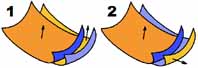
If your selection contains at least two surfaces or meshes (or clouds containing scanning direction allowing to determine the local orientation side to be best-fitted onto a surface), you will have the possibility to select the type of attraction that should be done between two overlapping areas. If you select Make attraction between all sides, an attraction will always occur between overlapping areas, whatever the normal orientation is. However, if you select No attraction between surface sides with different orientations, the best fit will only occur in the case of picture 1 and not in the case of picture 2.
A default threshold is defined by the software. However, you have the possibility to adjust this value if necessary by checking User-defined threshold. This threshold defines how far a point is considered as overlapping the one on the other object.If the conditions are fulfilled, you can apply an automatic pre-alignment by checking Pre-align in a first step.
You can add some constraints to the Best-Fit:
Rotations. You can:
Allow all the rotations: by default alignment behavior, no constraints will be applied.
Preserve the orientation of the X axis: the rotation will be only around the X axis, no rotation around Y and Z.
Preserve the orientation of the Y axis: the rotation will be only around the Y axis, no rotation around X and Z.
Preserve the orientation of the Z axis: the rotation will be only around the Z axis, no rotation around X and Y. If Z is the correct vertical in all your objects, as it will not move during the best-fit, the vertical will still be correct at the end of the best-fit.
Disable all rotations: the alignment will be only a translation.
Translations. You can disable each translation (along X, Y or Z) by unchecking the corresponding option.
If at least one translation is disabled, you will have to define the rotation center (by default it's the center of the bounding box for each object). Click on the purple circle to be able to click a point in the 3D scene. You can also modify the X,Y,Z fields manually.
Click Preview to see if the result fits your need.
Notes
The command applies the following rules to decide whether an option is available or not:
Legal objects to compute a new best fit are restricted to meshes, surfaces, clouds, geometric features and/or polylines. If your selection contains at least one entity that is neither a mesh nor surface, cloud, voxel, geometric features or polyline, the option Compute new best fit will be automatically disabled and Replay option will be selected.
You need at least 2 objects to Compute new best fit. If there is only one object in the selection, the option Compute new best fit will be automatically disabled and Replay option will be selected.
To make a ball radius compensation, the fixed object must be a surface. If this condition is not met, the option Compensate ball radius will be automatically disabled.
In some cases, the best fit can be applied without manual pre-positionning (Pre-align in a first step option available in advanced mode). The condition in which the automatic pre-positionning will work well is the case where the 2 objects that are to be best-fit together have a complete overlap. If this condition is not fulfilled, all the objects must be roughly pre-positioned so that overlapping zones are not ambiguous.
The resulting movement is described with 3 rotations also called "Euler angles". Here the angles are assumed to be applied in order Z->Y->X such that R = Rx.Ry.Rz, which is the most common convention. In addition, the command finds the point of the model having the greatest movement and tells you this distance, which is greater than all other points of the model.
The option Save matrix allows to save matrix result inside a file. Select the path and the name using the button '...'
Update coordinate system n°: When connected to a laser arm, this option allows to create or update the coordinate system the arm will use for the next measurements (commands Measure through RDS, Probe Feature).
Select the coordinate system number with the the arrow (up and down). You can define up to 9 coordinate systems. If a matrix already exists for the selected coordinate system, you can either:
Free so that this coordinate system is purely and simply deleted and replaced by this new alignment matrix.
Combine the existing matrix with this new alignment.
Tips & Tricks
If you have more than one object that must be used as reference immobile object, you must merge all these objects together to make a single object. You can do that using one of the commands Group Mesh or Merge Clouds, Extract Cloud. Remember that your original object remains accessible by restoring them from the recycle bin.
Practise
See the Exercise: Align a point cloud on a reference model according to the shape (Best Fit) in the Beginners Guide.