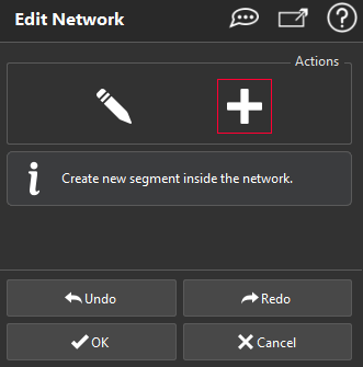
Edit Network
![]()
This command modifies an existing network.
Select the mesh and the network (polylines and / or set of polylines).
|
|
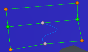
Colors are applied to nodes: Orange if only 2 segments are attached to the node Red if 5 or more segments are attached to the node Green if 3 or 4 segments are attached to the node |
 Modify network: move, select, delete nodes or change segment type.
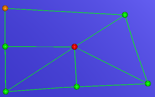

Select nodes and segments and delete them by pressing Delete or Backspace.
Double-click to replace a straight segment by a curved one, or a curved segment by a straight one.
- If a node is deleted, all attached segments will be deleted.
- If a segment is deleted, nodes at extremities are deleted if they are connected to 1 segment or less at the end of the removal .
Caution! Isolated segment and is olated node will always be deleted.
Move nodes. When a node is moved, all attached segments are also modified:
Segment with only one selected extremity
(segments are distorted, enlarged, ...)
Segment with the two selected extremities
(segments are translated)
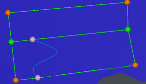
Straight segments stay straight, and curved segments stay curved.

When this option is activated, you have the possibility to create a new segment by clicking the extremities on existing nodes or segments. If you click on an existing segment, press Alt to keep the exact clicked point as extremity, else the extremity will be created on the closest point (between the 2 nodes or the middle of the clicked segment).
- If you want a straight segment (by default, color is the same as polyline), click only the 2 extremities. The created segment will be projected on the mesh, and added to the current network.
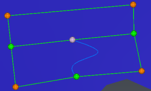
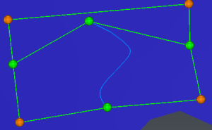
- If you want a curved segment (by default, the color is the same as bspline), click the first extremity + points on the mesh + the second extremity. The curved segment is displayed in blue, control points are displayed in red. Once the second extremity has been clicked, you have the possibility to adjust the segment with the control points. Click Enter when the segment has been correctly adjusted. The segment will be projected on the mesh, and added to the current network.