
This command creates a network of polylines on the selected mesh(es). For each input mesh, the resulting network of polylines is organized in a grid fashion and follows the mesh shape. You can then use this set to generate a patch or you can access each individual curve using the command Ungroup Polyline.
In order to launch the command, select all the mesh(es) on which you want to create a network of polylines.
|
|
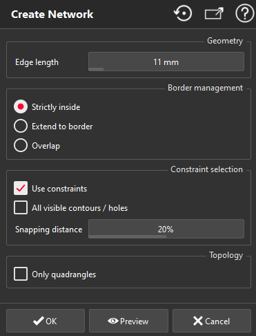
Launch the command.
Define the desired Edge length of the resulting network grid.
If you click on the Default button, the edge length will be computed as 1/20th of the bounding box size of selected mesh.
If there is at least one mesh with free borders/hole borders, select which kind of network you want (see below for illustration):
Strictly inside: this means that the network is regular and does not go to the free borders/hole borders.
Extend to border: this means that the previous network is extended to free borders/hole borders.
Overlap: this means that the first network is extended as a full grid beyond the free borders. In this case, the resulting network is also a regular grid.
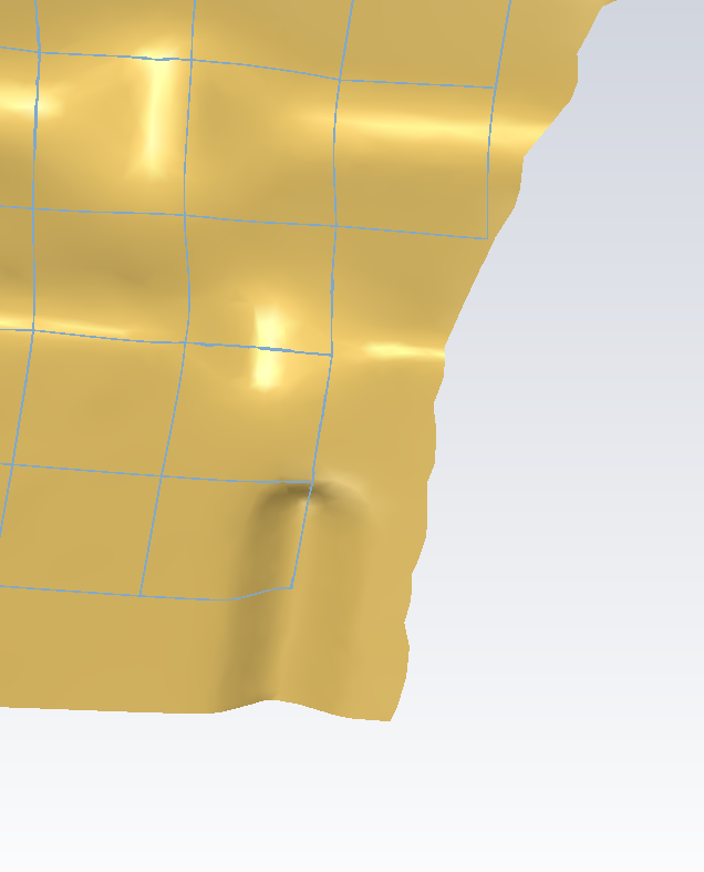
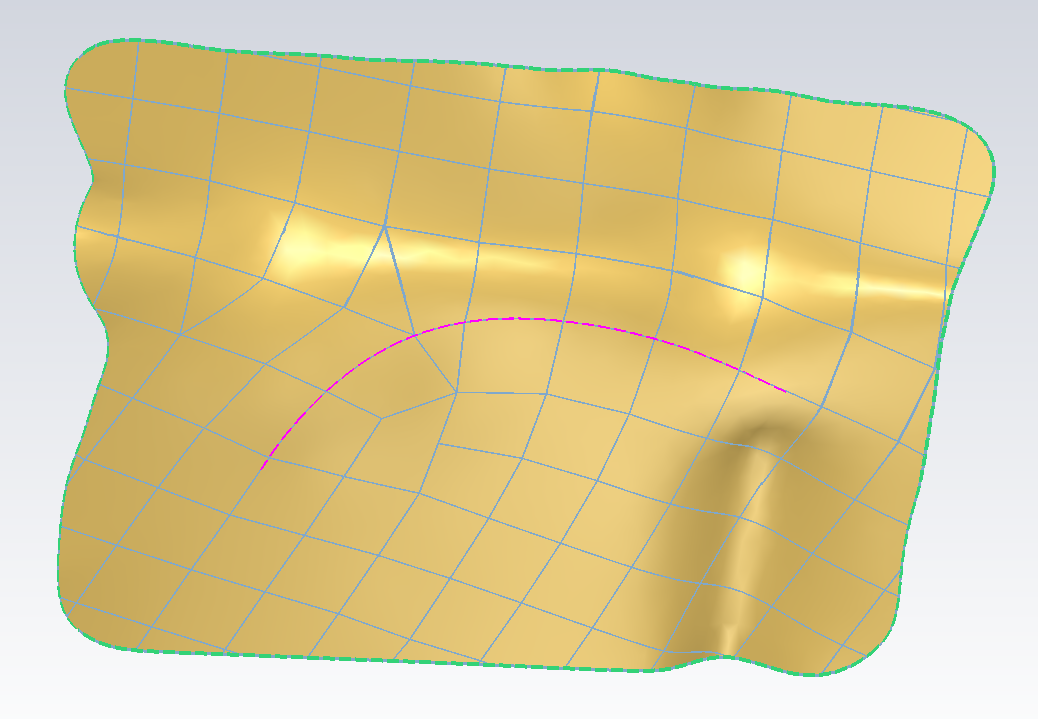
If you check the Use constraints option, the resulting network will tend to align its flow towards some desired input polylines. You can then select as usual any polyline or some mesh contours/holes. These polylines will be used as constraints for the network creation. If some polylines were selected before launching the command, the option is automatically checked. See below for an illustration of the constraints influence.
This option is only available when you enter the command with only one mesh.
If you click on the All contours / holes checkbox, All the contours and holes of the mesh will be selected at once. If you click again, they will be unselected.
Specify the Snapping distance percentage for the constraints. When you use constraints, the created network tends to align its flow towards the constraints, but the optimal solution is not necessarily exactly on the constraints. Whenever a network edge is locally close to the constraints (at a distance less than the pourcentage), it will be snapped to be exactly on this constraint. This snapping distance is expressed in percentage of the edge length.
Set the option Only quadrangles. With this option, the resulting network will be entirely made of quadrangles following the mesh. Without it, the network will be made of quadrangles almost everywhere, and some few triangles and pentagons.
Click on Preview if you want to see the result of the command.
Validate the command with OK, or, discard changes with Cancel.
If no polyline can be created, you will get a notifier.
|
Option for creation of network of polylines
|
Strictly inside
|
Extend to border
|
Overlap
|
|
|

|

|
Influence of the constraints
|
Without any constraint
|
With a polyline as constraint
|
|

|
|
Note
Limit objects manipulation is available in this command with CTRL+SPACE shortcut.