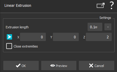
Linear Extrusion

images/download/attachments/113547010/CmdCADLinearExtrusion.svg

This command creates CAD surface(s) of profile(s) extruded along a direction, with a given length.

Select one or several profiles to extrude and launch the command.

A profile can be a CAD wire, a CAD curve, or a linear geometry.

images/download/attachments/113547010/image2019-9-24_15-10-30.png

  1. Enter the Extrusion length

  2. Choose the Extrusion direction. It can be achieved in 2 ways:

    1. manually enter the direction by specifying every X, Y and Z axis values

    2. click on images/download/thumbnails/113547010/Icone_chemin.png to define a direction

  3. Check Close extremities, if you want a closed CAD surface as output (If at least one profile is not planar and / or not closed, the option is not available).

  4. Validate the command by clicking on OK, display the result by clicking on Preview or close the command dialog by clicking on Cancel.

Example of a wire extrusion

images/download/attachments/113547010/image2018-8-27_9-42-29.png

images/download/thumbnails/113547010/image2018-8-27_9-42-20.png

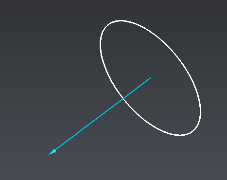
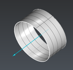
  • On the left: profile to extrude (white) and the extrusion direction ( blue arrow)

  • On the right: resulting CAD surface

Note

Limit objects manipulation is available in this command with CTRL+SPACE shortcut.