
This command creates a CAD surface corresponding to a profile extrusion along a path.
Select only a profile: in this case, you will have to select a path inside the command
Select first a profile and then a path
Both profile and path can be a CAD wire, a CAD curve, or a linear geometry.
|
|
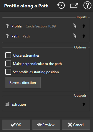
Check Close extremities, if you want a closed CAD surface as output
This option is available only if the profile is planar and closed, and if the path is not closed
Check Make perpendicular to the path if you want the profile to extrude
to be perpendicular to the first vector of the path.
Check Set profile as starting position if you want the extrusion to start at the profile position instead of path position.
Check the direction of the path and click on Reverse direction if necessary.
Validate the command by clicking on OK, display the result by clicking on Preview or close the command dialog by clicking on Cancel.
|
Note
Limit objects manipulation is available in this command with CTRL+SPACE shortcut.