This command creates a 3D mesh from selected point cloud(s). This command is designed for clouds acquired by a static 3D-laser scanner. A point cloud is acquired from one central point (scanner position) and 360 degree around. For this reason, the command is called "Spherical Mesh". These scanning conditions allow to optimize 3D meshing, for instance, the mesh orientation is (as far as possible) consistent with the scanner viewpoint.
Note
The following formats contain the scanning position and importing them in Cy3DR therefore allows to run this command in an optimized way:
Leica PTX format
Leica LandXml format
E57 format
Faro FLS format
Select cloud(s) to mesh and launch the command.
|

|
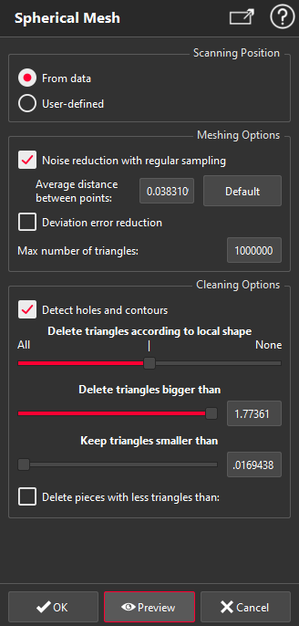
Set the Scanning position:
The command automatically retrieves scanning positions contained in selected clouds. If one or several scanning positions are found, the radio button is set to From data. Otherwise, From data is disabled, and the radio button is set to User-defined.
From data: create one mesh per scanning position.
User-defined: create one mesh per selected cloud. You can define one scanning position by clicking a point in the 3D scene or by clicking on Use current camera position.
If you want to create only one mesh with several point clouds with a User-defined scanning position, you will need to merge the point clouds before launching the command.
Define Meshing Options:
Noise reduction with regular sampling: Resample the cloud(s) to
keep only the best points. The bigger the Average distance between points is, the better the noise reduction will be (Obviously, the lower the level of detail will be). If you disable this filter, all the points of the clouds are taken into account.
Deviation error reduction: Keep in the mesh only the points needed to have distance with the cloud lower than the defined Deviation error value. However, this distance criterion is "statistic" and does not mean that all the points of the cloud will have a distance with the computed mesh lower than this value.
Max number of triangles: Define the maximum number of triangles in each of the resulting meshes. This parameter is mainly useful if you enter very low values for the two filters described above or if you disable the filters because it is possible to create very huge meshes.
Define Cleaning Options:
The spherical mesh provides in general many triangles in the scanning direction, which are not really on a valid surface. If your goal is to make a volume calculation, it may be relevant to keep those triangles to avoid filling all the holes. However in most cases, the goal is to delete those triangles.
Delete triangles according to local shape: Remove triangles which are not part of the surface. The automatic default value is often suitable. To remove more triangles, move the cursor to All, and to keep more triangles move it to None.
Delete triangles bigger than: Delete triangles having a size greater than this value.
Keep triangles smaller than: Never delete triangles having a size less than this value. This slider is used to keep triangles which can be delete with the first slider.
Delete pieces with less triangles than: Remove small pieces possibly obtained during the cleaning process to retrieve holes and contours.
If you modify one parameter in Cleaning Options group, the current computed mesh will be updated automatically without clicking Preview.
Validate the command with OK, display the result with Preview or close the dialog box with Cancel.
Scanning positions
Scanning positions are displayed in scene with one point and 8 arrows. One color is defined for each scanning position and its computed mesh.
When validating the command, points corresponding to scanning positions are added in the 3D scene.
|
