Surface Flatness
![]()
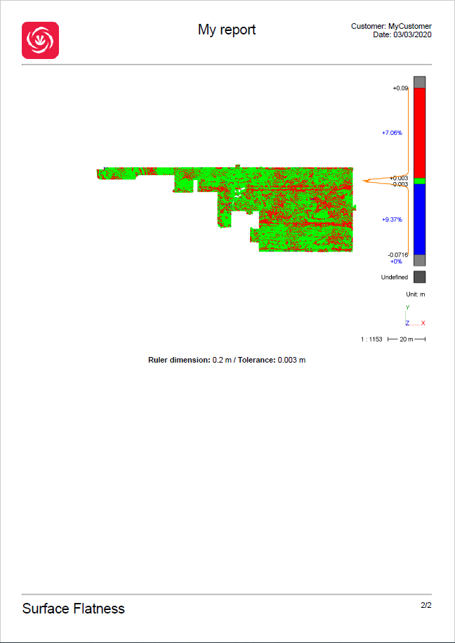
This command allows you to inspect the flatness of a mesh or a point cloud. An inspection value will be associated to each point of the cloud or vertex according to the local flatness.
The algorithm moves a cylinder aligned to the Z axis all along a regular grid covering the object surface. The ruler radius corresponds to the cylinder radius.
For each cylinder position, a best local plane is computed.
Then it compares points inside the cylinder to the local plane so as to evaluate the flatness of the associated area according to a given tolerance.
Select the mesh or the cloud on which you want to analyze the flatness and launch the command.
Tip & Trick: measure the flatness of a wall
You have to create first (and activate) a User Coordinate System with a Z-axis perpendicular to the wall.
Note
You can also launch this command, without selection, to analyze the levelness of planar parts of a cloud or a mesh. See paragraph "Compute the analysis on a planar area extracted from a mesh or a cloud" at the bottom of this page.
Define the ruler dimension as well as the tolerance to be respected.
Press Preview to preview the results.
Validate and exit the command with OK.
Note
The calculated inspection value is local. It means that the flatness calculated for each point only considers its neighbors within a maximum distance of half the ruler dimension.
Note
A default color map is proposed with 2 thresholds: green for points inside the tolerance, red for points above the tolerance (points are above the ruler) and blue for points below the tolerance (points are below the ruler).
A report