Exercise: Create a 3D mesh of the Samothrace Victory
Open the file Victory.3dr.
This file contains two point clouds: one Victory + noise with some measurement noise, and one Victory already filtered with the command Noise and ready to mesh (see Exercise: Clean a cloud using automatic filters).
Explanation about hole management
Whatever the selected meshing method, options concerning the hole management are the same. You have the choice between three modes:
Hole detection: enter the size of the smallest hole you want to keep.
Try to keep the external border: all the holes will be filled, except the external border.
Try to create a watertight mesh: the result will be a closed mesh (without any holes).
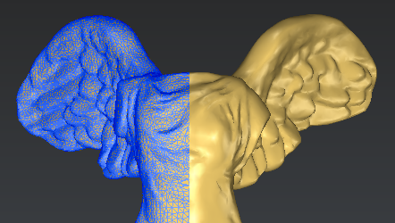
 Holes management during the 3D mesh
From left to right:
the cloud to mesh
hole detection
keep only the external border
try to create a watertight mesh
You can find more information about holes in the Exercise: Fill holes with curvature filling.
Regular Sampling
Select the cloud Victory and launch the command 3D Mesh. Then, select the option Regular Sampling and Try to create a watertight mesh. The field Average distance between points is filled automatically according to the point cloud properties (size, number of points, etc.). Then click Preview to visualize the 3D mesh.
The regular sampling method will project a grid on the cloud and select the most representative point inside each square of the grid. Then it computes a 3D mesh from all the selected points.
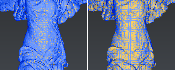
Change the representation mode to Flat + Wire in order to see triangles shapes. You will notice that they are quite regular and equilateral. The value set for the Average distance between points roughly determines the size of the grid projected on the cloud. In this case, the value is approximately 0.6 mm and corresponds to the average distance between vertices.
Change the Average distance between points to 2 mm, so the grid will be 3 times bigger than before. Have a look at the triangles shape: they are quite big but still regular.
 Regular Sampling: this method creates regular meshes where the size of the triangles depends on the average distance between points
In some cases, a regular sampling is not the best choice:
if the level of details is not the same all over the mesh, or
if you enter a small average distance on a cloud with some measurement noise, or
if the final result appears too facetted.
In these cases, you can use the Meshing in two steps.
Meshing in two steps
The goal of this method is to create a mesh in two steps:
first, we create a rough mesh in order to get the global shape without any holes or errors,
then, we stretch this rough mesh according to the point cloud in order to add all the details.
Select the cloud Victory and go to 3D Mesh. Then, select the option Meshing in two steps and Try to create a watertight mesh. The field Average distance between points is filled automatically according to the point cloud properties (size, number of points, etc.). Then click on OK to compute the first rough 3D mesh.
The dialog box corresponding to the second step will be opened automatically once the rough mesh is computed.
There are three Refining methods:
Refine from Cloud Interpolation; if your point cloud contains a lot of points and/or noisy points (measurement errors), it is strongly advised to interpolate new points.
Refine from Cloud; will give you better results if the point cloud contains only precise points and if you want to preserve sharp edges.
Refine without Cloud: this method does not use the point cloud, it is not useful in this workflow.
For this exercise, only the first two methods will be used and explained.
Select the option Refine from Cloud Interpolation and Refine with deviation error as we do not care to have points evenly spaced. This option will create new points according to an estimation of the best shape to create. Then set the Deviation error to 0.05 mm, it means that the maximum distance between the mesh and a “perfectly smooth” surface will be less than 0.05 mm. There are 2 other parameters in order to control the refinement:
Maximum number of triangles; in order to avoid having too many triangles in the mesh. Enter 1 million.
Minimum triangle size; in order to avoid very small triangles in the mesh. Enter 0.5 mm, this value should be bigger than the deviation error.
Set the other parameters as following:
Distance; to reject the points located too far away from the polyhedron you can enter 1 mm.
Local reorganization; to give a better mesh of sharp angles and small fillets you can select it.
Select No free border modification.
Click on Preview to compute the refined mesh. Once it is finished, you can have a look at the triangles shape by changing the representation to Flat + Wire: triangles are not regular now, their size depends on the details.
 Refine by interpolating new points
Now change the Refining method and use the Refine Mesh from Cloud option and Keep only best points as there is still some noise in the cloud. Enter 0.05 mm for the Deviation Error in order to compare with the previous method. Set the Distance to 1 mm and check Local reorganization. Check No free border modification and click on Preview to refine the mesh.
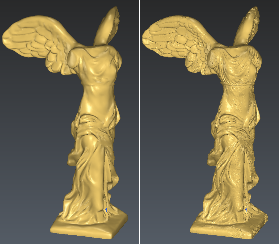
As you can see in the next pictures, the mesh is spikier, so we added some noise to the mesh. In order to avoid this, we should try again with a bigger deviation error. This noise does not appear with the method Refine from Interpolation because it has been reduced during the computation of the new points.
 Comparison between the two refinement methods; Left: Interpolate new points: Right: Take points of the cloud
In order to avoid spiky results, the deviation error must always be bigger than the scanner accuracy when you use the option Refine from Cloud.