3D Meshing & Cubature
Introduction
In the software, several meshing commands are available. It is essential to choose a strategy regarding the final purpose of the mesh. A refined mesh is needed to have a good looking result, but the goal is different for a volume computation, for example.
Exercise overview
In this exercise, we will see how to create meshes of a point cloud with different levels of details, and we will compare their volumes.
Steps included in the exercise:
Create a 3D Mesh with all the points,
Create the 3D Mesh of a point cloud with a regular sampling,
Refine a 3D Mesh thanks to a point cloud,
Compute volumes of a mesh,
Compute cubature between two meshes.
The file used in this tutorial is 3DMesh&Volumes.3dr
Overview
The file contains two point clouds, which are quite different, as they were measured with distinct methods:
The point cloud of a stockpile (a bit more than 2 150 000 points)
A point cloud composed of exact points measured on a reference plane (platform of 172 points).
The second cloud contains very few exact points whereas the first cloud contains a lot of points, and probably some noisy points. We will first see how to mesh each of these point clouds with the appropriate method.
Mesh the points of the platform
The reference plane contains few but accurate points. In this way, we will mesh it by keeping all the points.
Select the cloud of the reference plane (Platform).
Launch the command 3D Mesh. As there are only a few points in the cloud, the option Keep all the points is checked by default.
Choose the option Keep all the points.
For the hole management, choose the option Try to keep only the external border as we do not want any holes in the plane.
Click OK to compute the result. The mesh is displayed and the point cloud is hidden.
Right click on the created mesh and check the Properties. You can see that the mesh contains as many points as the cloud, and only one free contour (the external border).
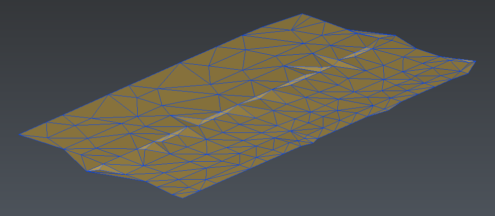 Figure 1: Mesh and point cloud of the platform
You can right click on the mesh to display the contextual menu and choose the representation Flat + Wire to see its triangles. If the mesh appears blue with gold underneath it means that it has its normal reversed. You can select the mesh and press i to reverse it, so that the top appears gold.
You can also change the color of the mesh: right click on it and go to Color.
Now we are going to mesh the stockpile. We will create two meshes in order to compare the volume computation with a rough mesh and with a refined mesh.
Create a rough mesh of the stockpile
Select the point cloud of the Stockpile.
Launch the command 3D Mesh.
Choose the option Regular Sampling and enter 0.35m as the Average distance between points.
Choose the option Try to keep only the external border because we do not want holes in the mesh.
Click OK to compute the result.
If you right click on the mesh and open the Properties, you will see that it has 10 holes or free contours. Here, we only want one contour representing the external border, so we are going to fill all the other holes.
Select the mesh and go to Fill Holes.
Select all the holes except the external border. You can also select the Select borders shorter than option and enter 61m for the Length to automatically select all the holes.
Choose to fill the holes with Curvature filling.
Click Preview and OK, Exit to compute the result.
If there is still more than one independent pieces, you can select the mesh and use Ungroup Mesh to automatically separate the independent parts. Delete the smallest and keep working with the biggest.
Put the mesh in the Flat + Wire representation mode to see the triangles. They have a regular placement.
Select the mesh and go to Global Smoothing, in order to smooth and reorganize the triangles.
Select the option Smooth noise and choose a low smoothing Intensity (approximately 25% of the slider).
Uncheck Control deviation, Improve curvature areas and Smooth free borders.
Click Preview to see the smoothing.
Click OK, Exit to validate the result.
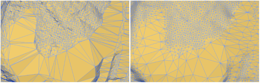 Figure 2: On the left: the rough mesh. On the right: the rough mesh after smoothing
The first rough mesh of the stockpile is now satisfactory. It should contain nearly 100 000 triangles. We are going to keep working on this mesh, so create a copy of it, rename it Rough mesh and hide it in order to save it for later.
To create a copy of an object, select it, right click and click on Copy. Then right click in the 3D scene and click on Paste.
Create a refined mesh of the stockpile
We are going to use the previous mesh to create a refined mesh of the stockpile thanks to the point cloud.
Select the mesh and the point cloud. It is not needed to display the point cloud.
Launch the command Refine Mesh from Cloud Interpolation.
Choose the option Refine with deviation error in order to control the deviation error between the points and the mesh. Set a deviation error of 0.001m. This value is low to retrieve the details.
Limit the number of triangles to 1 million to avoid having too many triangles.
Set the Minimum triangle size to at least 0.01m to avoid having triangles that are too small.
Set the Distance to 0.2m.
Check the Local reorganization to have triangles placed along the edges.
Choose No free border modification as the mesh does not have any hole.
Click Preview and then OK, Exit to compute the result. You should obtain a mesh with 1 million triangles.
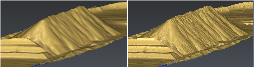 Figure 3: On the left: the rough mesh. On the right: the refined mesh
You can go to Split View Vertically in order to display two different views in the software. The active view is surrounded by a thick border. Click in the left view to set it as the active view. Select the Rough mesh, right click on it and select Show only. In this way, only the rough mesh is displayed on the left, and only the refined is displayed on the right.
Compute and compare volumes
Now we are going to compute several volumes with both meshes in order to see the differences between the computation with a rough mesh and the computation with a refined mesh.
The rough mesh is quite smooth and does not have many details, whereas the surface of the refined mesh is really precise. On the other hand, the refined mesh contains also some noise, as it has been refined with the point cloud including noise.
We are going to see if it is really necessary to have a refined mesh or not for volume computation.
We will first compute volumes thanks to a level of water, then volumes between the meshes and the reference plane.
Volume over a given height
Select the rough mesh and go to Volume from Elevation.
Check the option List of values and enter 337m for this example.
A transparent blue mesh appears in the scene to represent a water level.
Hide this plane.
Click Preview to compute the volumes over and under this water level.
A Results window shows the 2 volumes computed and the difference between them.
Check the Label(s) as output and click OK to validate.
A label is created in order to give volumes above and below the plane. Now repeat the same process for the refined mesh. You can keep working with two views, so in the left view hide the labels referring to the refined mesh and vice versa.
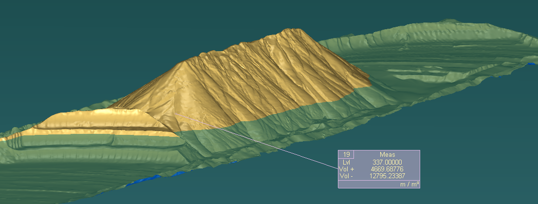
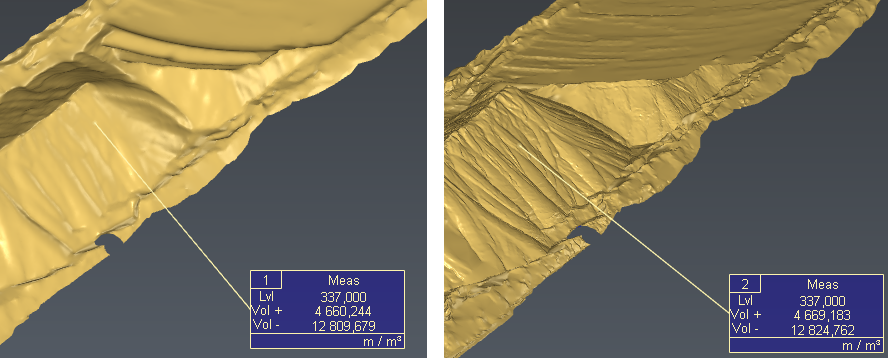 Figure 4: Volumes over and under a water level on the rough mesh (left) and on the refined mesh (right)
Difference of volumes between the rough mesh and the refined mesh:
Over the water level: 9 m3 -> 0.19% of the total volume
Under the water level: 16 m3 -> 0.12% of the total volume
Volume between two open meshes
Hide all the labels in both views, and display the reference plane that we have meshed in the first step. We are now going to compute cut and fill between the meshes and the platform.
Select the rough mesh and the reference ground.
Launch the command Cut and Fill.
Choose a direction to compute the volume between the meshes. Here we want the direction to be Z, so click User defined input and then click the Z button in the tool dedicated to vector input.
Click Preview to compute the results.
Volumes computed and difference between them are given in the Results window. It also warns you that the volumes are approximated because the meshes do not have the same borders, so some parts of the surface are outside of the free borders. The message also interprets the volumes as excavation and embankment depending on which mesh is seen as the reference.
Click on OK to validate.
Two labels are created in the 3D scene. One indicates the volume above the platform and under the Stockpile. The other indicates the volume above the Stockpile and under the platform. Now repeat the same process for the refined mesh.
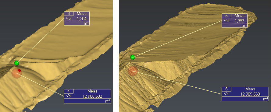 Figure 5: Volumes between the platform and the rough mesh (left) and the refined mesh (right)
Difference of volumes between the rough mesh and the refined mesh:
Above Stockpile and below Platform: 0.8m3 -> 40% of the total volume
Above Platform and below Stockpile: 4 m3 -> 0.03% of the total volume
Conclusion
In this example, we can see that the differences of volumes are extremely low compared to the total computed volumes. So we can conclude that a refined mesh is not necessary here to compute the volume of the Stockpile.
To compute volumes, the level of details needed in a mesh actually depends on the tolerance fixed for the volume computation.
But it is important to keep in mind that if a mesh is more refined, the noise of the point cloud will be taken into account in a more important way. To have a very accurate and very detailed mesh, a clean point cloud is needed.
On top of that, a very refined mesh contains much more triangles, so the data are heavier, and the computations can be longer.
To go further
It is also possible to compute a liquid volume all over the mesh according to regular slices. The resulting volumes can be displayed through labels and customizable report or can be directly exported in CSV format. The intersection lines between each plan and the mesh can also be extracted via the Extract menu and Intersection.
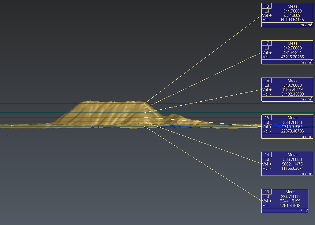 Figure 6: Example