Create and use a Digital Terrain Model
Introduction
Creating the model of a terrain is a very common job in Surveying. However, it is not always an easy task dealing with scans of a whole area containing also vegetation and/or buildings. The application brings an automatic solution to extract the ground out of a point cloud.
Exercise overview
In this exercise, we will see how to create a mesh of a terrain, directly from the global point cloud. Then we will see how to use this mesh of the ground to create contour lines and to extract breaking lines such as curbsides.
The SURVEY Edition is needed for these computations.
Steps included in the exercise:
Create a 3D Mesh of the terrain,
Extract only points on the ground,
Create contour lines on a mesh,
Extract all the breaking lines in a mesh,
Export polylines.
The file used in this tutorial is GroundMeshing.3dr
Overview
The file contains two point clouds, representing two different types of terrain:
A road going through a steep ground in the forest.
An urban area with small houses, pavements and few trees.
The first terrain is quite steep whereas the second is fairly flat. We will see how the same function can be used to extract the ground from both clouds.
Extract the ground from the steep terrain
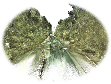
Have a close look at the cloud SteepTerrain. You can set the view in Perspective mode to fly through the cloud over the road.
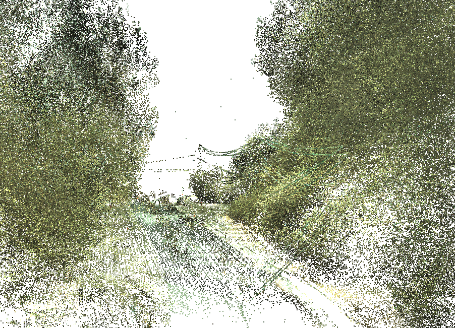 Figure 1: Visualize the cloud in Perspective mode.
Several methods could be used to clean the point cloud in order to get the model of the ground around this road. The solutions are more or less manual and time consuming. In the software, there is a completely automated function to directly create a mesh of the ground from the entire point cloud.
Select the cloud SteepTerrain.
Launch the command DTM.
Set the Max slope on 48° as the ground is quite steep.
Choose the option Z as direction.
Set the Extraction grid size to 0.8 m.
Choose Check noisy points as extraction strategy.
Choose the Refined meshing strategy.
Uncheck the point clouds checkboxes.
Click Preview to compute the result.
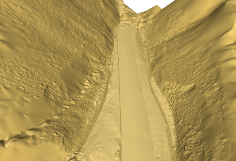
The mesh is displayed after few seconds. You can change the representation mode of the mesh to set a smooth display.
Click on OK to validate the results.
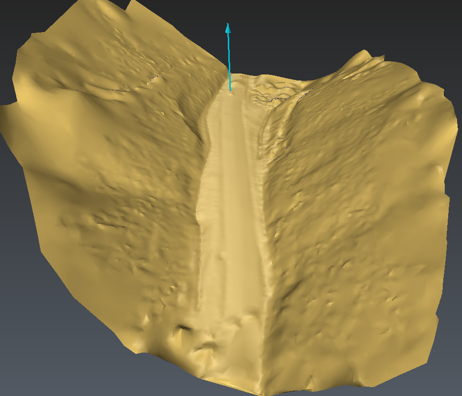 Figure 2: Creation of the mesh of the ground surface.
It is also possible to extract the points on the ground or the points not on the ground (vegetation, building).
To have more details on the parameters, please have a look at the Help files by clicking on the question mark in the dialog box.
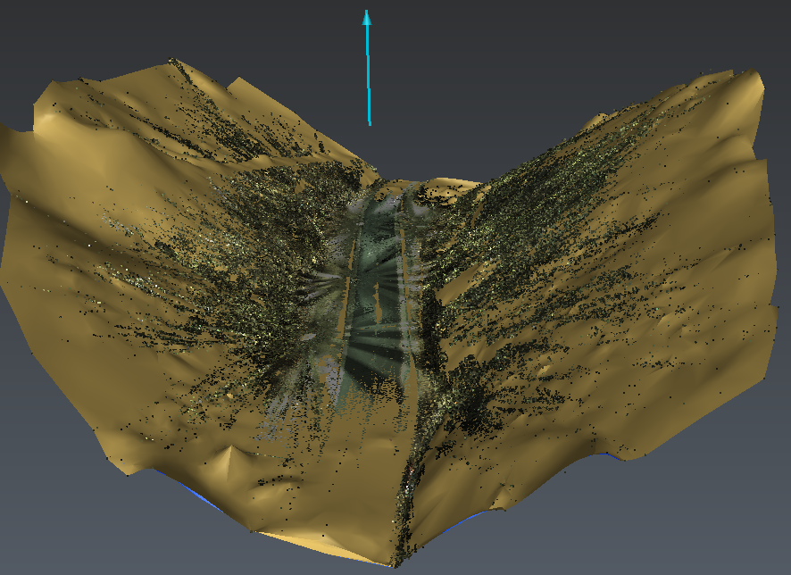 Figure 3: Extract points on the ground.
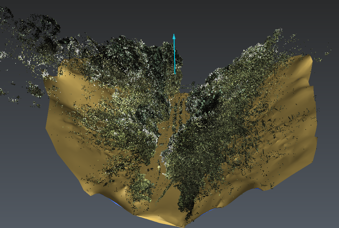 Figure 4: Extract points NOT on the ground.
Create contour lines on this terrain
Now that we have the DTM of this terrain, we can create its contour lines.
Select the mesh of the ground.
Launch the command Contour Lines.
Define a Step of 2m and a Major contours frequency of 5.
Choose to Create sections all over the mesh.
Don't check Pass Through option.
Click Preview to compute the result and OK to validate. The created polylines are all grouped in one set of polylines.
You can adjust the width, the color and the display of the text for the normal and for the major contours.
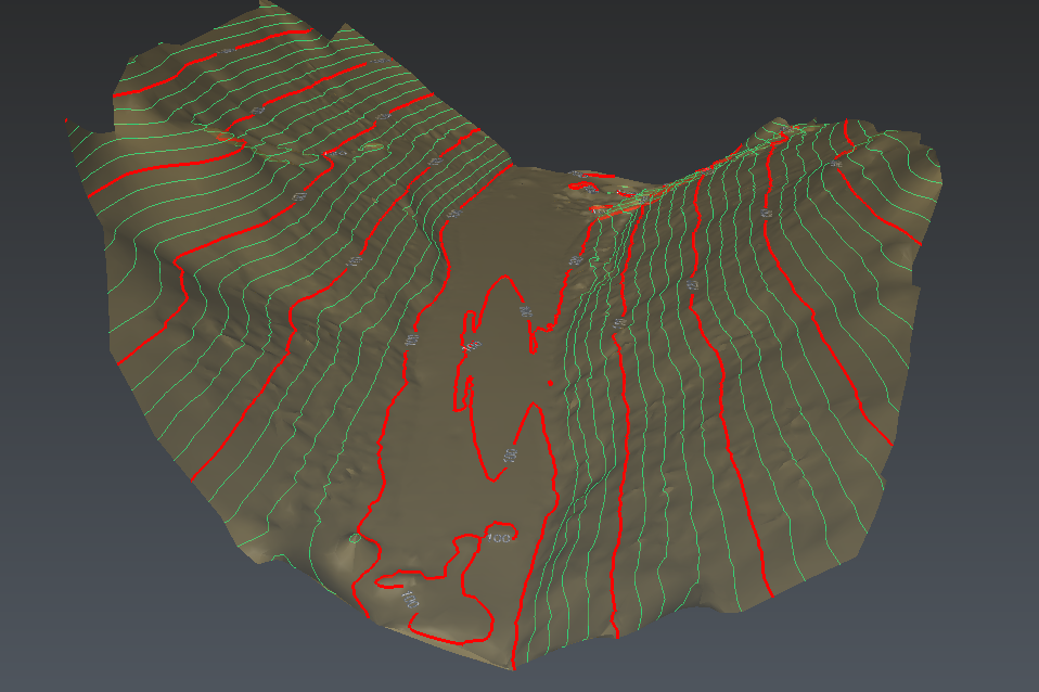 Figure 5: Create contour lines every 2 meters.
You can export this set of polylines in a DXF format. Select all the polylines; go to Export. Choose where to save the file, click on Export to do the export.
Extract the ground of the flat urban area
Now show only the point cloud UrbanArea. We have here a completely different type of landscape and we are going to see how to create a mesh of the ground only.
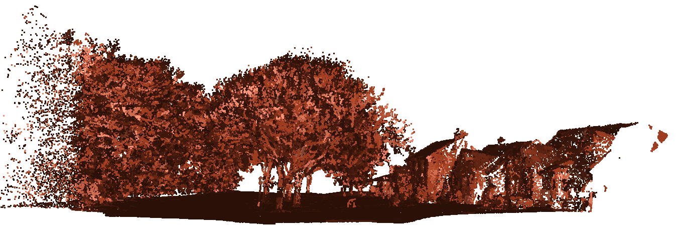 Figure 6: Point cloud of a street with houses and trees.
Select the cloud UrbanArea. Press A to center the model in the graphic scene.
Launch the command DTM.
Set the Max slope on 25° as the ground is quite flat.
Choose the option Z as direction.
Set the Extraction grid size to 0.6 m.
Choose Check noisy points as extraction strategy.
Choose the Refined meshing strategy.
Uncheck the point clouds checkboxes.
Click Preview to compute the result.
The computation takes approximately one minute.
Click on OK to validate the results.
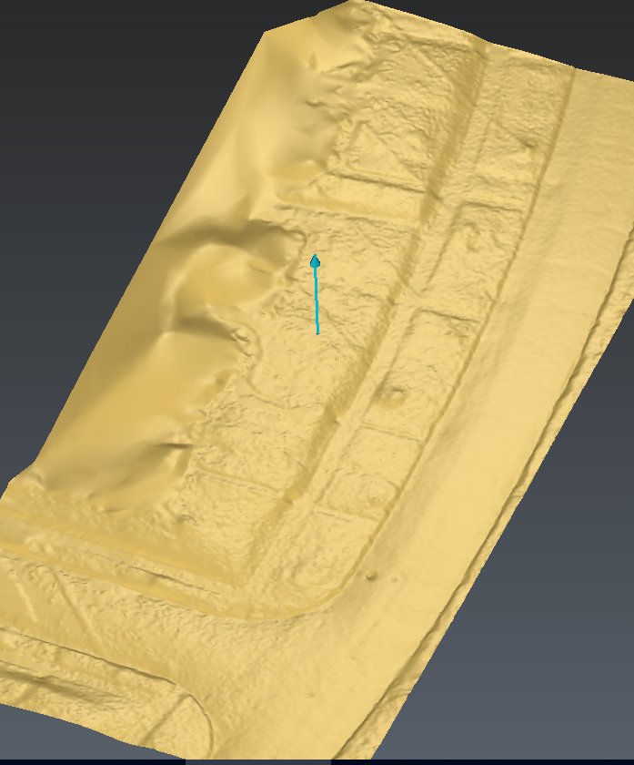 Figure 7: Ground mesh of the street.
Extract the edge of the pavement
Now, we have the DTM of this terrain. We can extract the breaking lines such as the curbsides or road lines.
Select the mesh of the ground.
Launch the command Multiple Breaking Lines.
Click directly on Preview to see all the breaking lines which can be extracted.
Then, modify the Relevancy parameter to filter the result and get only the desired lines.
Uncheck and hide the Convex polylines by clicking the bulb.
Click OK when the preview suits you.
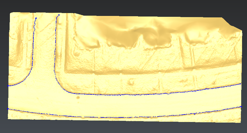 Fig 8: Extract breaking lines
The blue lines are detected on concave curves. They are all put in one set of polylines. By zooming in on the results, we can easily see that the extracted lines ripple as they follow the mesh. So we need to smooth the polylines.
Select the set of polylines.
Launch Smooth Polyline.
Choose Hard smooth option, with 10 as Smoothing intensity.
Uncheck all other options.
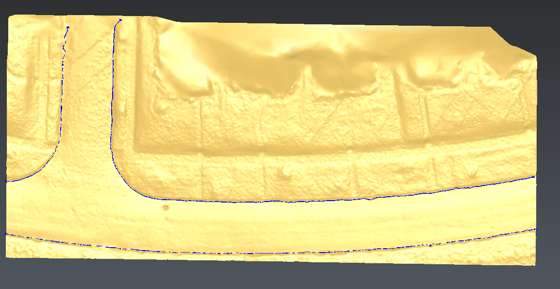 Fig 9: Smooth the polylines
At the end, this set of polylines could be exported in DXF format to use it in a CAD software and create the 2D drawing of the street.
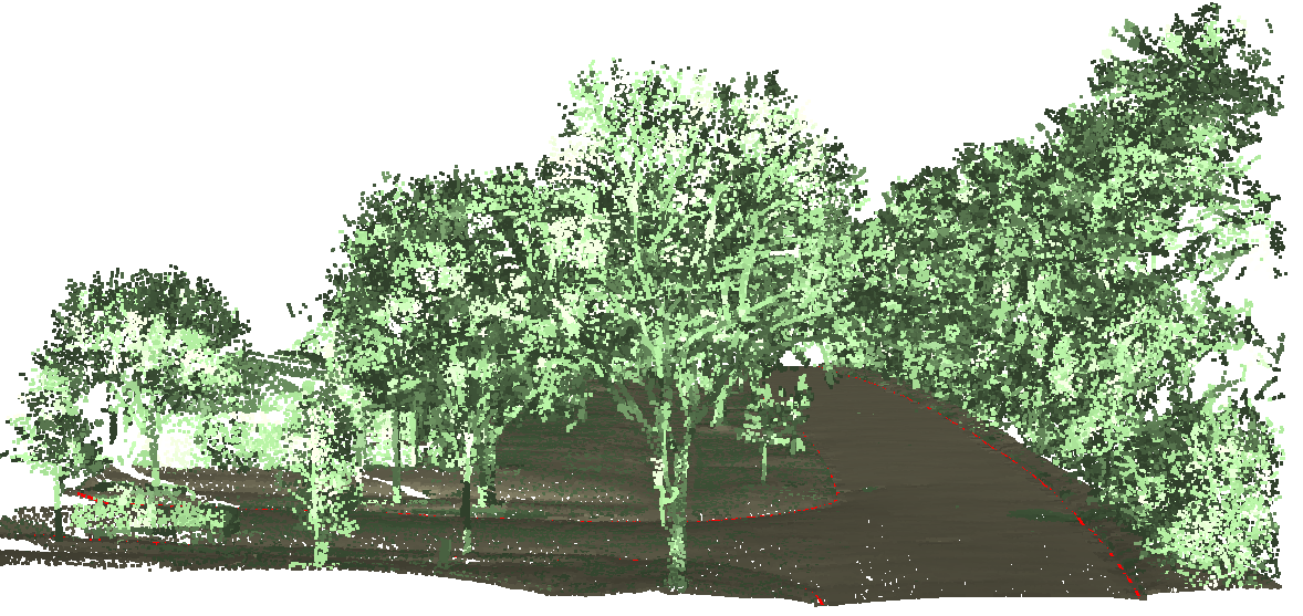 Figure 10: Extracting the limit lines of the pavement.
You can also use Single Breaking Line to manually extract or project between 2 points the line following the mesh curvature.