3D Meshing and Texturing
Introduction
In the software, several meshing commands are available. It is essential to choose a strategy regarding the final purpose of the mesh. Several steps can be required to generate a good looking and accurate result, especially if the cloud contains noisy points. The texturing provides a realistic rendering of the 3D polygonal model and can improve consequently the aesthetic aspect of the final model.
Exercise overview
In this exercise, we will see how to create a good mesh using different steps because of the point cloud features. We will also texture the mesh and decimate the number of triangles in order to export a lighter weight realistic model.
Steps included in the exercise:
Create directly a precise 3D Mesh and see the possible resulting issues,
Create a rough 3D Mesh to prepare the subsequent steps,
Refine a 3D Mesh with the real points to add details,
Refine a 3D Mesh with new points to improve the surface,
Project and map an image onto the surface,
Reduce the number of triangles and export the textured mesh.
The file used in this tutorial is Capella.3dr
Overview
The file contains one cloud of about 1.5 million points with an irregular density, holes and noisy points. Points are measured approximately every 4 mm.
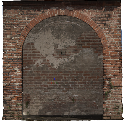
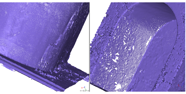 Figure 1: View of the cloud density.
Making a first mesh to see what happens
If all points were exact, we could mesh them all. However, this statement is not true and also it would lead to a very big mesh containing twice as many triangles (3 million).
Select the cloud.
Launch the command 3D Mesh. Choose the options Regular Sampling 0.01 and Try to keep only the external border as we do not want any holes.
Click OK. The mesh is displayed and the point cloud is hidden.
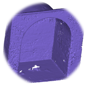
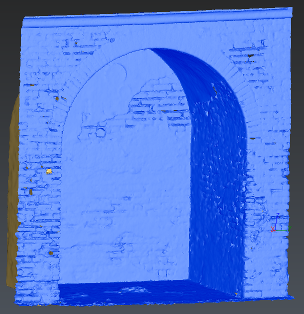 Figure 2: Meshing with a high reduction noise. Regular sampling at 0.01.
You can see that the mesh contains fewer points than the cloud, as a point has been selected every 1 cm.
You are now ready to analyze your first result.
Many holes are present in zones where there were no points.
Complex shapes might make the dozens of holes difficult to fill.
The level of details is sufficient but the mesh is not aesthetic (around 315000 triangles).
Some noisy points have been meshed creating independent pieces.
The surface is quite faceted and not smoothed as it should be. A smoothing could be carried out to improve the visual aspect, but the properties of the mesh would remain the same.
The conclusion of this first test is:
Regarding the holes and the noisy points, it would require meshing with a bigger triangle size.
About the level of details, it would require to keep a small triangle size.
The problem is that these two actions are contradictory. It means that we will not be able to treat the two problems at the same step. The constraint regarding the holes and noisy points is more important than the other one because it is always better to start with a mesh having the good topology.
Making a rough mesh
A mesh should be done with a larger triangle size to pass over the holes:
Make undo (CTRL-Z)
Select the cloud
Launch the command 3D Mesh. Choose the options Regular Sampling 0.06 and Hole detection
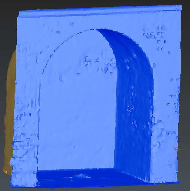 Figure 3: Meshing with a small reduction noise (rough mesh). Regular sampling at 0.06.
The rough mesh is quickly generated and has only 2 contours or remaining holes for 1 piece. The overall shape is preserved although the details are missing.
You can also fill the holes:
Select the mesh
Launch the command Fill Holes
Click on the hole inside and Preview.
This function is detailed in the exercise Meshing a dam.
Refining using the points of the cloud
Since the details are not visible in the rough mesh, we need to take directly the points of the cloud to refine the mesh.
Select the mesh and the corresponding cloud
Launch the command Refine Mesh from Cloud
As the point cloud contains a high number of noisy points, we will Keep only the best points only and a Deviation error of 0.001
Put 0.01 in Distance to disregard the distant points
Check the Local reorganization.
Choose No free border modification
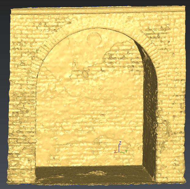 Figure 4: Refining using the points of the cloud
The level of details seems good as there is no hole in the one-piece model. The only problem is found in the jagged aspect of the model. The result is very faceted, spiky and noisy. However, if you make a “standard” smoothing, you will see that most of this noise can be removed (Global Smoothing).
The issue of this smoothing is that it tends to deform the model and to transform the sharp edges in radii. This is the reason why we will not keep this result.
Cancel the smoothing operation if you have launched it.
Refining with new points interpolation
As all the details are present in the shape, even if it is noisy, it is now possible to optimize this mesh to find the “best” smoothed surface in the middle of the noise thickness.
Select the refined mesh and the cloud
Launch the command Refine Mesh from Cloud Interpolation
In the meshing generation method, take Refine with deviation error
Enter 0.0005m as deviation error and 0.001m on minimum triangle size
Enter 0.01m as outlier point Distance
Check the Local reorganization.
Choose No free border modification
Click OK, Exit
The result should be really nicer.
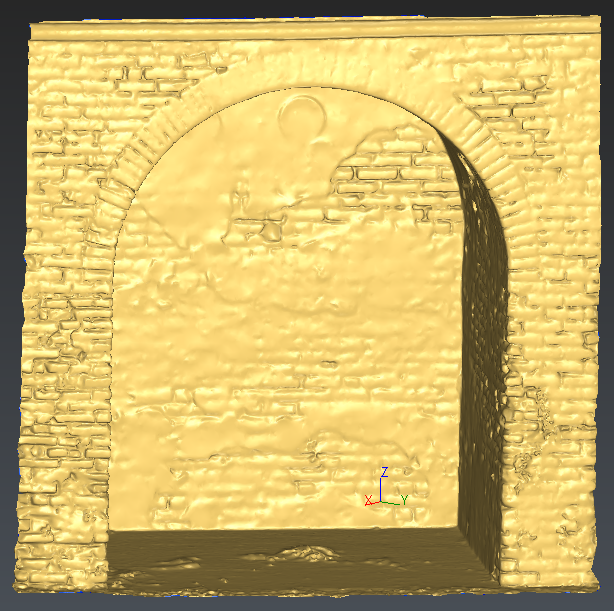 Figure 5: Refining with new points interpolation
Texturing the mesh
Import the perspective image Cappella.jpg
Select the image and launch the command Estimate Pose
Now you have to select several pairs of points: one on the picture and one on the 3D model to adjust the image on your mesh. We advise to choose reference points such as the circles, the bottom corners to make the points coupling and the projection easier and more accurate. The points should also be scattered all over the model. You can move and zoom on the image. Select as many points as you think necessary for the projection.
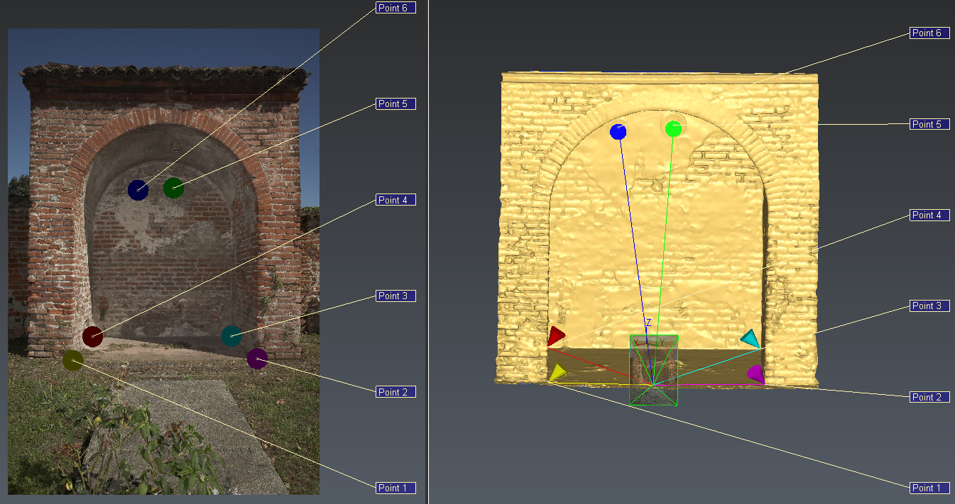 Figure 6: Textured mesh
Then select the image and the mesh and launch the command Standard Texture. Select Invisible parts and validate.
The mesh is now textured. Through the contextual menu (right click on the model), you can swap the Representation mode and come back to the non-textured mesh.