Create building plans
Introduction
Thanks to new laser scanners, either static or mobile, drawing 2D/3D plans of an existing building, thanks to a point cloud, is probably a very common task you have to deal with. You may use to draw manually on ortho-images or on cloud slices. This practical exercise shows how 2D plans can be drawn in an assisted way.
Exercise overview
In this exercise, we see how to create 2D plans and elevations. The AEC license is required for these computations.
Several steps are included in this exercise:
Define the slices,
Extract, draw and edit the polylines,
Export this drawing to another CAD software.
The file used in this tutorial is ScanToPlans.3dr
Overview
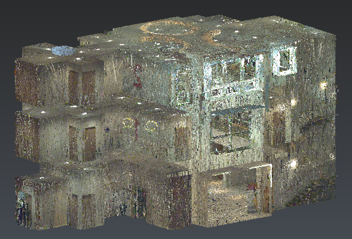
This file contains the point cloud of a 3-level building that was measured with a Leica BLK2GO. Thus, panoramic images have been recorded while measuring. The cloud has been resampled to achieve a mean distance of 1 cm between points, nevertheless the following workflow can be performed with higher density.
A UCS has been defined parallelly to the building, activate it, then select the cloud and launch the workflow Scan to Plan.
Slice definition
In this first step, you will define where to draw building sections with the Advanced mode.
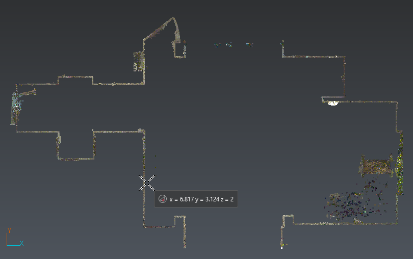
Set the slice direction to Z=1. Select the option List of values and click the blue cross. You can either enter a value or click an elevation in the 3D scene. In perspective mode, you can go inside this building to understand its architecture and pick appropriate elevations. In orthographic view, press X or Y key to pick levels thanks to an elevation view. Here is a list of useful sections to combine:
|
Level |
Distance (m) |
Thickness (m) |
Comment |
Suggested name |
|
0 |
2 |
0.2 |
main section |
0-Main section (Z) |
|
0 |
3.1 |
0.2 |
below ceiling |
0-Below ceiling (Z) |
|
1 |
3.8 |
0.2 |
floor |
1-Floor (Z) |
|
1 |
6.15 |
0.2 |
main section |
1-Main section (Z) |
|
2 |
7.3 |
0.2 |
floor |
2-Floor (Z) |
|
2 |
9.7 |
0.2 |
main section |
2-Main section (Z) |
|
2 |
10.3 |
0.2 |
ceiling |
2-Ceiling (Z) |
When the list is fulfilled, set the default slice thickness (20 cm) and click on Insert slices. They are added to a list of slices where you can rename (which is highly recommended, the names will be exported as well) and modify them. You can adjust their positions and their thicknesses through the 3D scene.
Now, you can add vertical slices:
|
Direction |
Distance (m) |
Thickness (m) |
Comment |
Suggested name |
|
X |
11 |
0.2 |
central area |
Central area (X) |
|
X |
18.4 |
0.2 |
stairs |
Stairs (X) |
|
Y |
2 |
0.2 |
stairs |
Stairs_a (Y) |
|
Y |
6 |
0.2 |
stairs |
Stairs_b (Y) |
Finally, set the resampling step to 5 mm and click Compute. This will project the points on defined planes and then resample the clouds to eliminate duplicate points. That is why the initial point cloud density can be higher or lower than this sample. Click NEXT button to validate and start plans extraction.
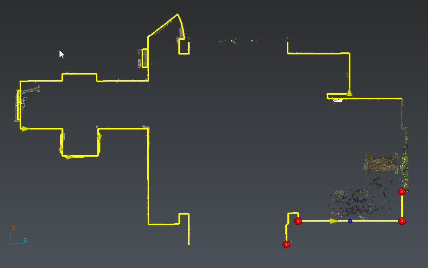
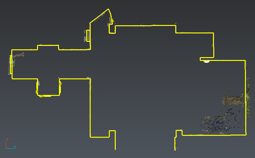
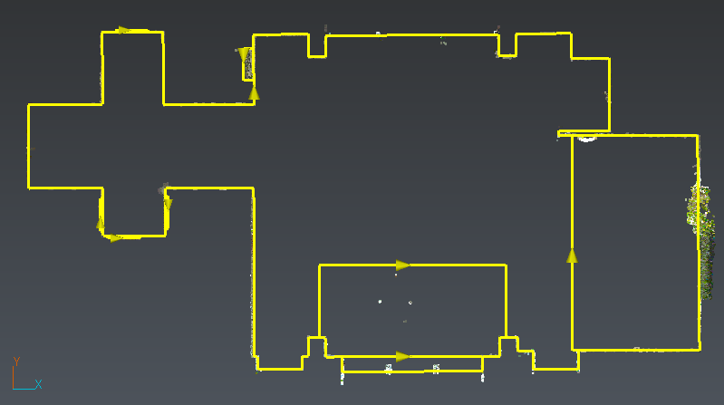
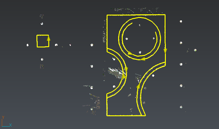
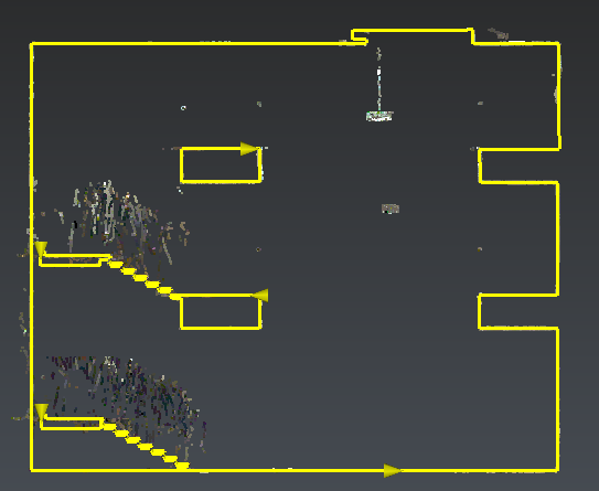
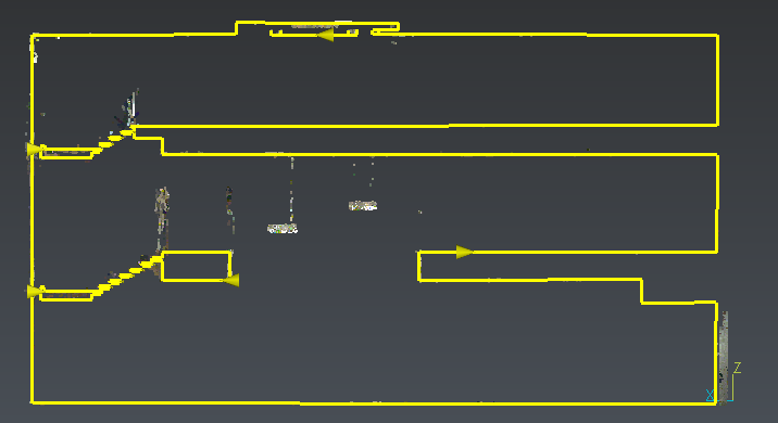
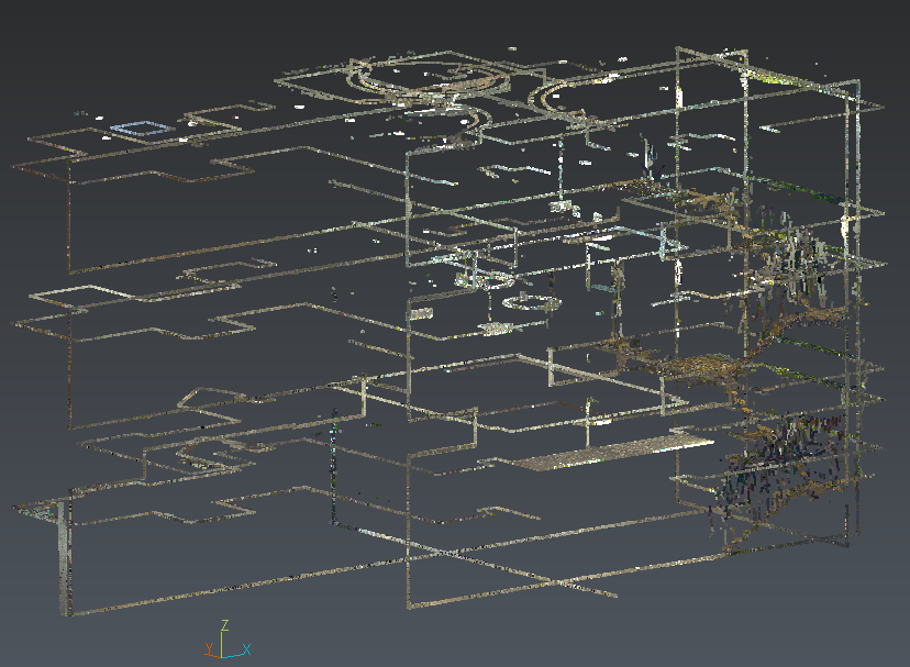 Fig1: extracted slices
Extract plans: level 0
|
|
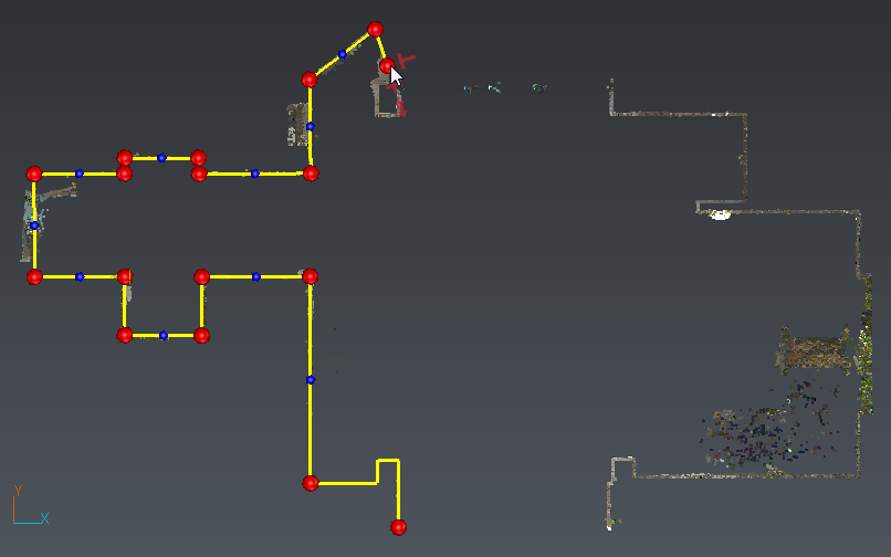
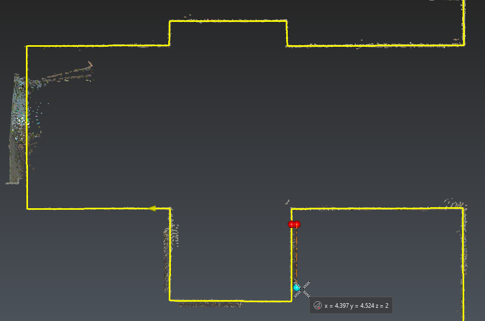
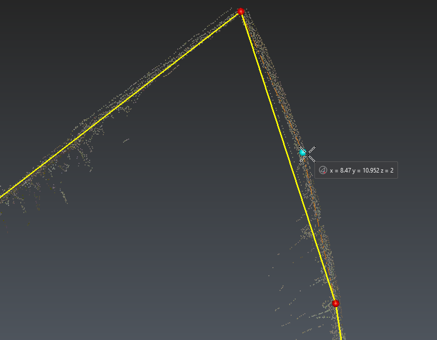
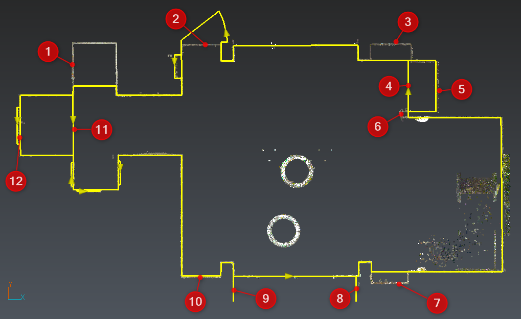
Select the slice 0-Main section (Z) and Extract the external contour. Set a 0.05 m Resolution and activate the Simplified extraction. Choose seed points in straight lines. The resolution parameter should be set approximately to the half of the wall thickness to detect each side. 5 cm should fit most cases. Note: if the mean distance between points is too high or if you have missing areas in your point cloud, the extraction will stop automatically. In such cases, switch to Manual extraction to continue. |
|
|
The automatic extraction finds the corresponding wall and the neighboring ones. The points used by an extraction are automatically hidden (and cannot be used again for automatic extraction). To check the extraction, click the funnel button to display them. Each extraction can be modified manually (refer to Edit Polyline). For instance when the extraction ends in a noisy area, press DEL to remove selected vertices. Note it is possible to select several vertices thanks to a rectangular selection, regardless if they are displayed with a red ball or not. |
|
|
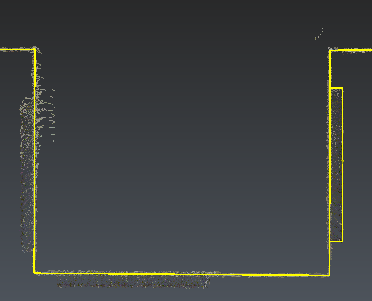
Automatic extraction of details requires clouds with high resolution and accuracy. Draw manually the doors. You can either press CTRL to draw segments parallel to the UCS or create a first segment lying on an existing polyline and then add perpendicular segments. |
|
|
To extend a segment to another polyline, either with perpendicular tool or extend tool, press SPACE until Intersection mode is activated. Finally, click the second polyline. |
|
|
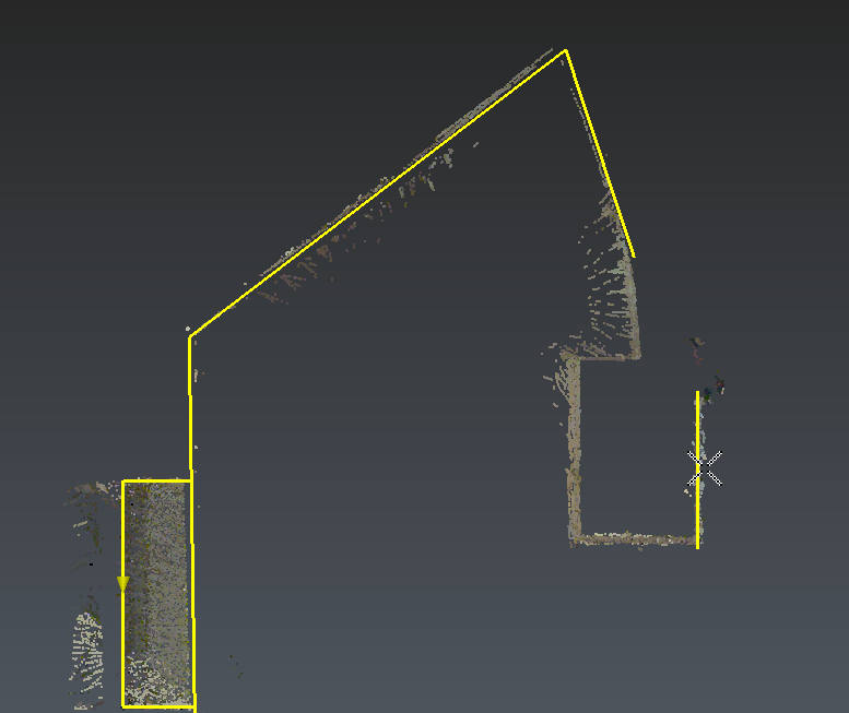
Continue the extraction using Quick Draw mode:
|
|
|
Give 4 seed points, press ENTER to validate and switch to edition mode. Add another segment and snap the other polyline extremity: both polylines will be merged. |
|
|
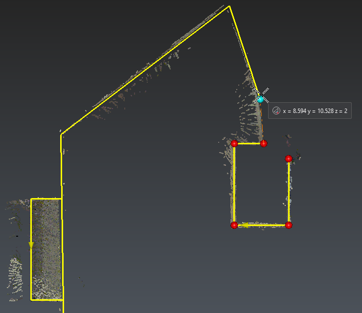
Use the small blue ball to add vertices in curved areas. You also can drag and drop red balls to adjust vertices position. |
|
|
Complete 0-Main section (Z) drawing. Because of a noisy area (wall with vegetation), the extraction may stop. Edit one polyline (select it and launch Edit or simply double-click on it), then launch the extend tool, press SPACE until Junction mode is activated. Finally, click the second polyline. Both polylines will be merged at their intersection. Note the Junction mode is also available in the perpendicular tool. |
|
|
This floor is almost done. Copy this level to 0-Below ceiling (Z). This level has been automatically activated and you can complete 0-level with other details which could not be seen on the first slice. |
|
|
Level 0 is complete. At any time, you can exit the workflow and visualize the whole 3D cloud to improve our understanding of the building. Later, it will be possible to resume the workflow. |
Extract plans: level 1
|
|
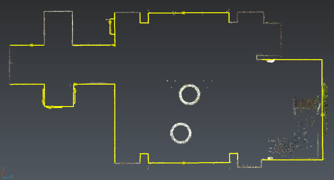
Once Level 0 is done, copy it to level 1-Main section (Z). You should notice some differences between Level 0 and 1:
Select polylines 4, 11 and 12 either through the scene or the list and remove them using the red cross or DEL. Double-click the polyline to edit 8 and 9 extremities: shorten them using vertex/end snapping mode. The polylines will be merged and closed. |
|
|
Split the polylines (1, 2, 3, 5, 6, 7, 10 and 12) to remove incorrect parts. Note it is possible to move several vertices with a drag and drop instead of that. |
|
|
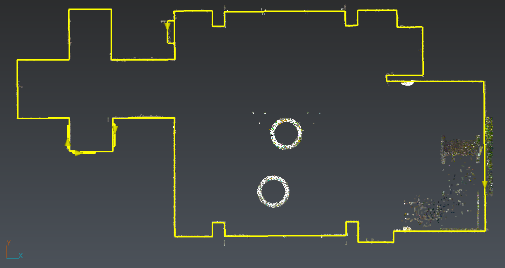
Then edit the polylines to complete missing parts. Finally copy these polylines to the slice 1-Floor (Z) |
|
|
Using Quick Draw, complete Level1 with both floor contours. Shorten them, then extend them with Intersection mode. Note that each level can be slightly or totally different, thus it is often not necessary to start a new level copying the previous one. It depends also on the accuracy and level of details that you want. |
Extract plans: level 2 and vertical sections
Optionally, complete plans extraction with 2-Main section(Z), 2-Ceiling_a (Z), 2-Ceiling_b (Z), and the 4 vertical slices. Try also the Copy tool to draw repetitive patterns such as stairs.
|
Level 2 |
Details on the ceiling (Level 2) |
|
|
|
|
Central area (X) |
Stairs (X) |
|
|
|
|
Stairs_a (Y) |
Stairs_b (Y) |
|
|
|
Click NEXT button to validate and start next step.
Export 2D Plans
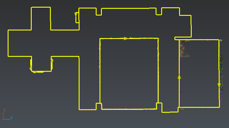
At this step, you can generate a DXF file, send the polylines to AutoCAD or generate a FML file. Choose to export a DXF. Then you will be able to add texts, hatches... and complete your plans and elevations.
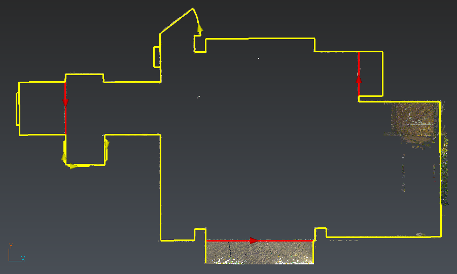
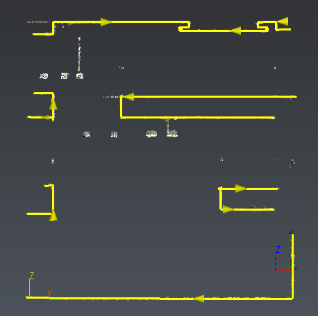
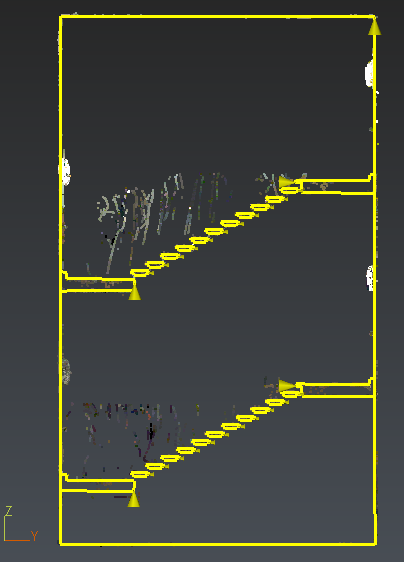
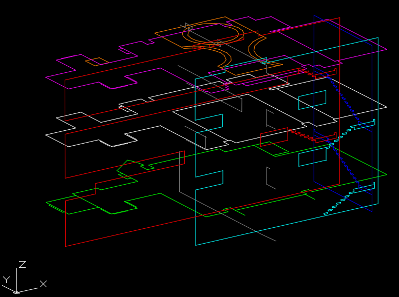 Fig 2: DXF (main levels, ceiling and vertical sections)