Building extraction
Introduction
Some applications require simplified models which are light and easy to handle, keeping the best accuracy. The software brings an easy guided solution to extract planar surfaces in order to create the simple model of an object, a building, a whole street.
Exercise overview
In this exercise, we will see how to create the simple model of a building, directly from the global point cloud. Then we will see how to create sections over the building and also export the created elements. The SURVEY Edition or AEC Edition are needed for these computations.
Steps included in the exercise:
Create a simple mesh of the church,
Edit the created surfaces and edges,
Create sections on the model and
Export model and polylines.
The file used in this tutorial is BuildingExtraction.3dr
Overview
The file contains the point cloud of a church. This point cloud has been extracted from pictures taken by an Aibot UAV from Leica Geosystems (https://leica-geosystems.com/products/uav-systems).
The file imported inside the software was a LAS file, containing 3D coordinates as well as RGB colors for each point. The cloud is displayed here in the Real Color representation mode.
Extract walls and roofs of the building
We are now going to create the model of the church by using only one function. The idea is to click on each planar surface one after the other to extract walls and roofs. The function will automatically join the surfaces and create the accurate model of the church.
Select the cloud Church.
Launch the command Building Extractor.
The function automatically preprocesses the cloud to find the best Extraction tolerance that you can see at the top of the dialog box. You can modify this value to extract particular planes if needed.
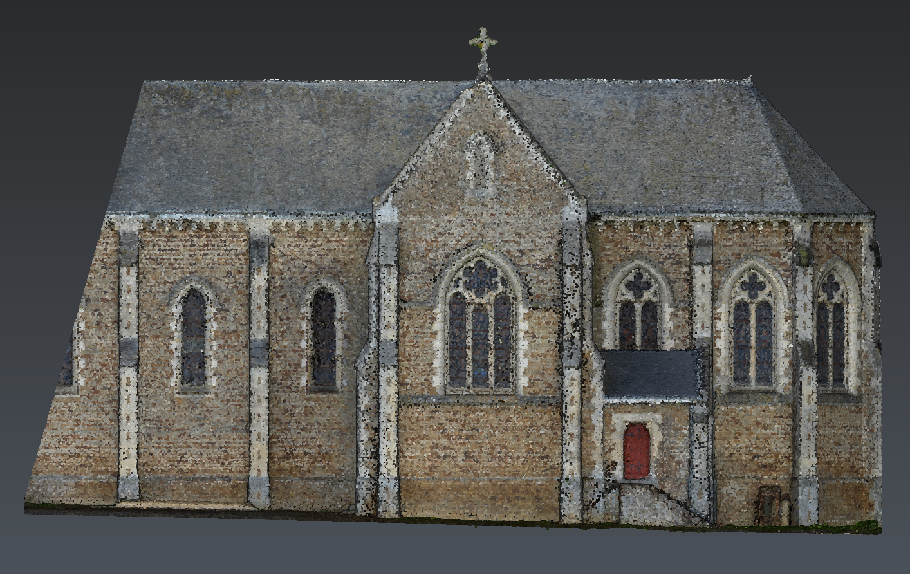 Figure 1: The Building Extractor guides you to create the model
Click on the first part of the roof to extract (left click on the point cloud). The computation is done automatically. You will briefly see the best plane that has been computed, and then you see a thick line showing the contour that has been found.
Press ENTER on the keyboard to validate this contour.
A planar mesh is created, having the same borders as the contour.
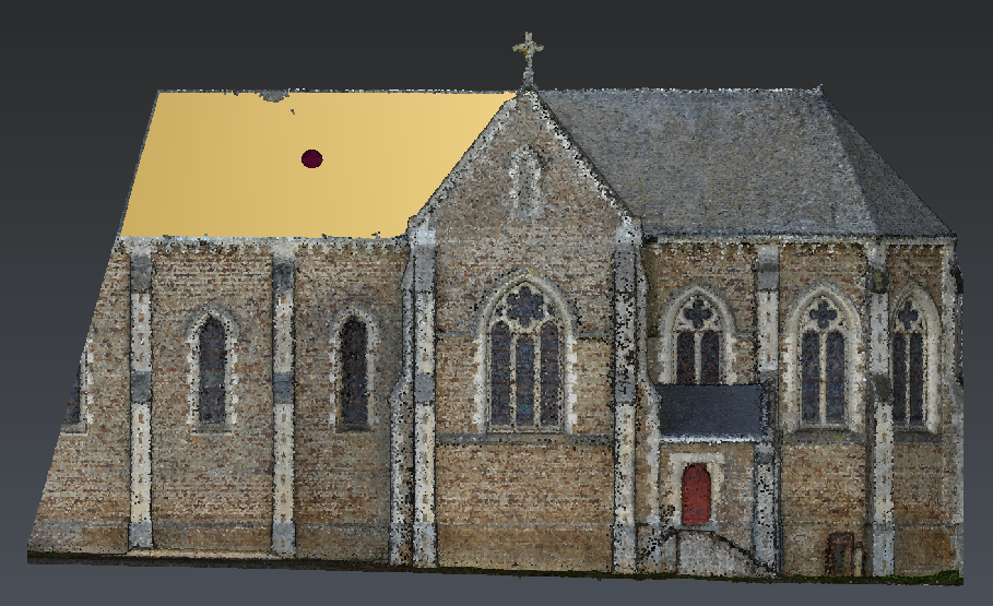 Figure 2: Click on the point cloud, then validate the contour with ENTER.
Turn the view and click on the adjacent roof to extract.
Validate the contour by pressing ENTER.
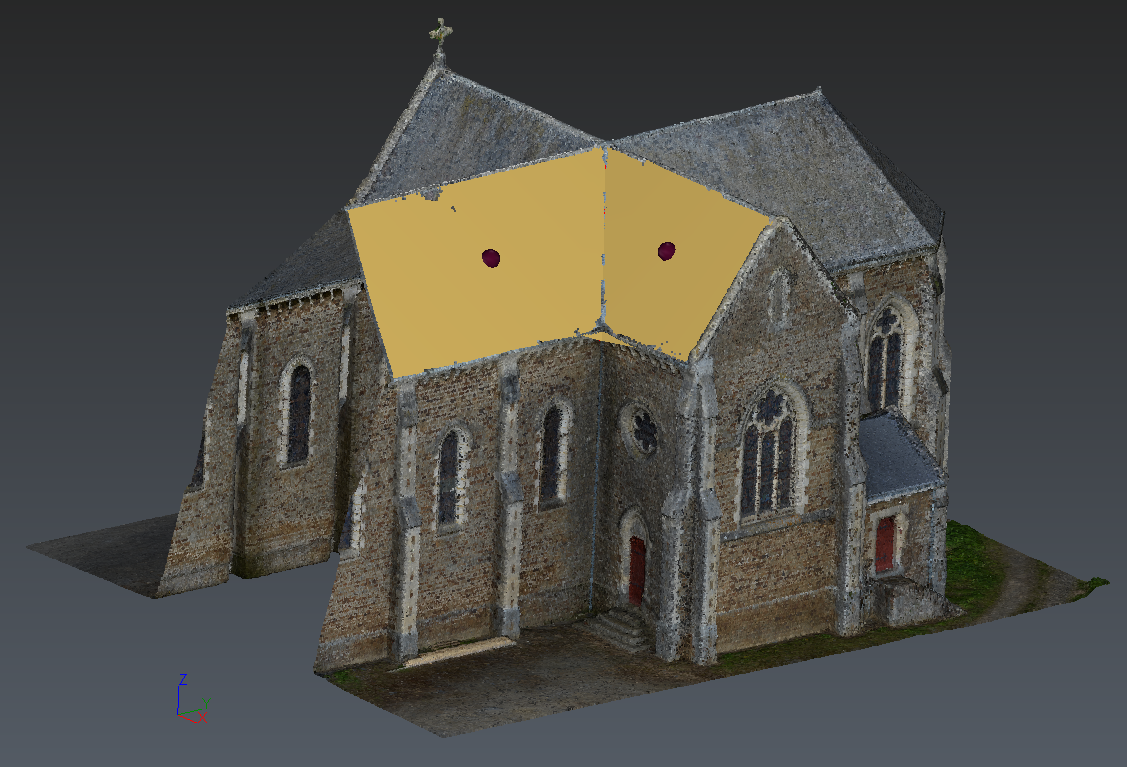 Figure 3: The two planar surfaces are automatically linked together. The red line shows their intersection.
Now click on a vertical wall.
You can see in the dialog box that the options Fit vertical plane and Fit plane normal along X axis are now written in bold. This means that the detected contour is nearly vertical and is nearly aligned on the Y axis (normal along X). If you select this option, you force the detected surface to be perfectly vertical.
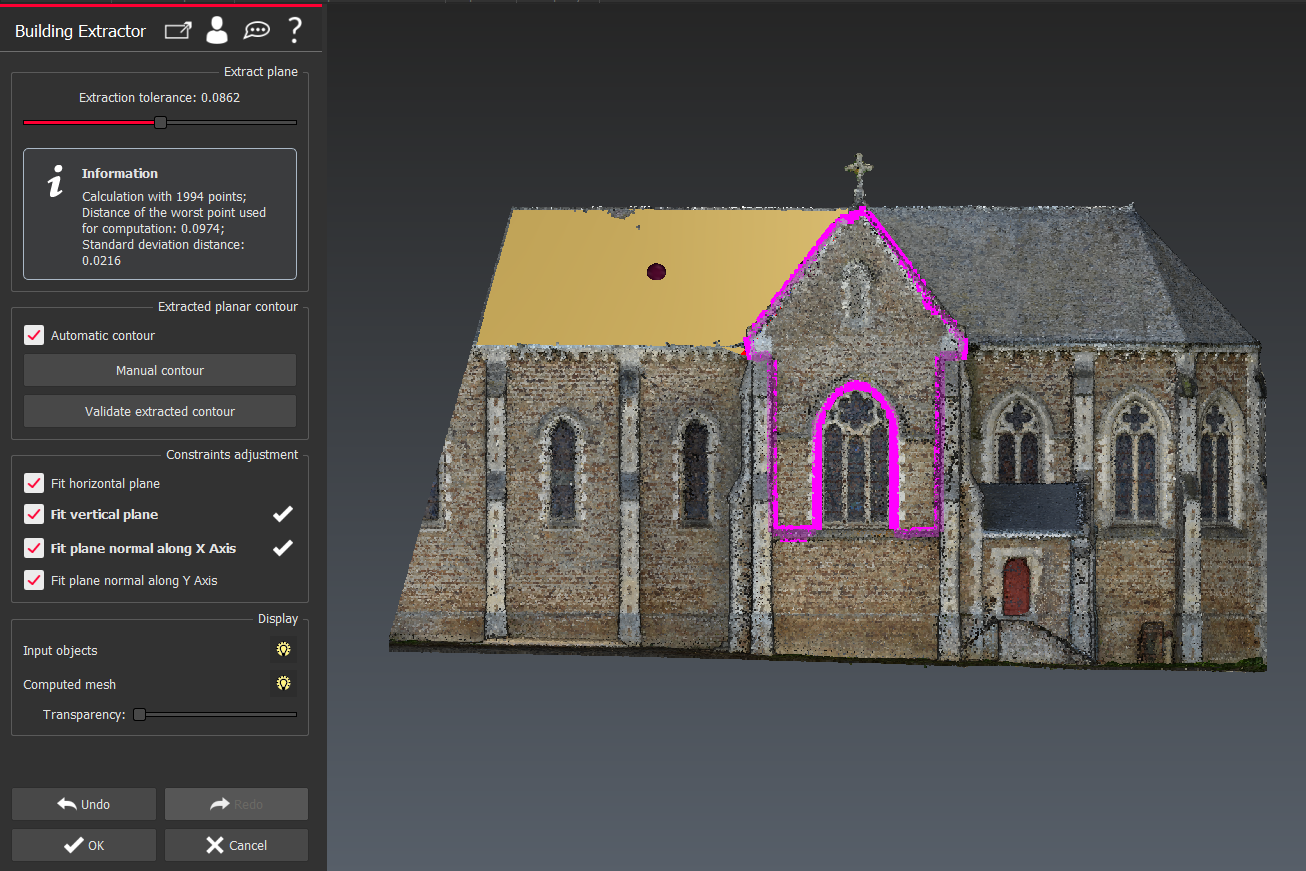 Figure 4: Option Fit vertical plane and Fit plane normal along X axis
Press ENTER to validate the contour.
Repeat the same procedure for each surface that you want to extract from the point cloud.
For each new surface that you click and validate, the software will compute its intersection with the other existing planes and link the surfaces together.
While in the command you can press Ctrl+Z at any time to undo the last face you extracted from the cloud. You can do this several times if you like.
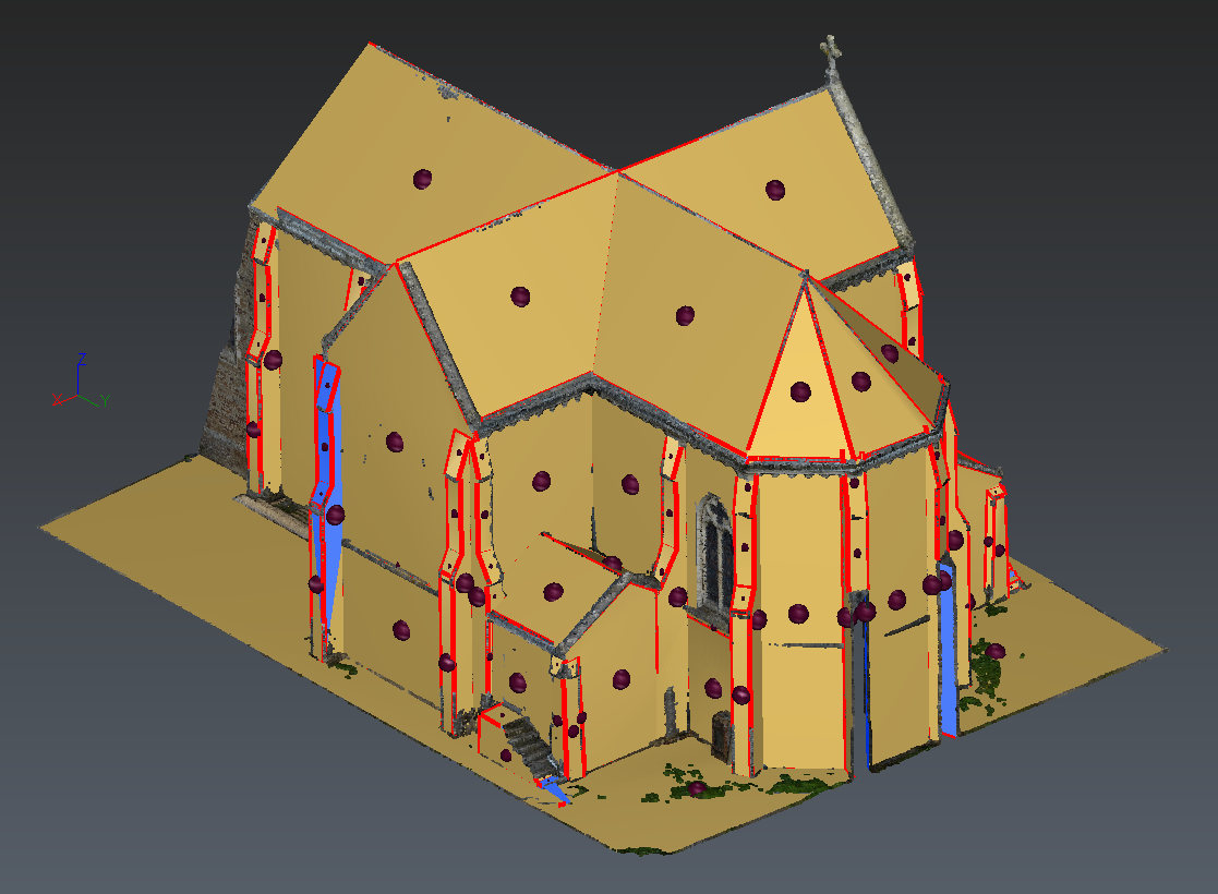
Once you have created all the surfaces needed, click on OK to validate the results.
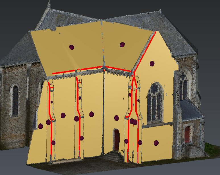 Figure 5: First results
A new folder is added to the tree: ExtractedBuilding1. It contains all extracted surfaces (ExtractedMeshes), computed intersections (ExtractedEdges) and used contours.
If the extraction is not complete, it is possible to continue it by selecting this folder and the original point cloud before launching the Building Extractor function.
The function will automatically re-compute the generated surfaces and their intersections. Then you can continue to extract the other surfaces, and they will be added into the same folder.
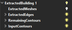 Figure 6: folders in tree
While you are inside the command, you can see that there is a control point displayed on the center of each surface, and the detected edges are displayed with double arrows. These tools help you to force or delete links between surfaces.
If a link is missing between 2 surfaces, you can force the link by dragging the center ball from the first surface on the center ball from the second one.
If the function has created a link that you do not want, you can click on the edge and press DEL on your keyboard to delete it.
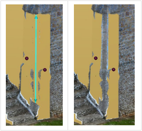 Figure 7: remove a link created by default
If the detected contour is not the one you are expecting, you can switch to Manual Contour. Then you can click points to define the contour exactly the way you want. The points that you click will be automatically projected on the computed best plane. So the manual contour will still be planar.
Several shortcuts can be used in this function. You can display them by clicking on  in the dialog box. See the Help files for more detailed explanations.
Create the 2D plan of the church
If you have created the complete model or only a part, you can now create a section over the model to get the 2D floor plan of the church.
After creating the simple model with the Building Extractor tool, you could use Fill Holes to fill small holes where data was missing to extract the surface
Select the mesh and launch the command Planar Sections.
Choose Z Direction for the plane direction.
Choose List of distances and set 1. You can also use the button at the left of the list and click a point on the model, at the elevation where to create the section.
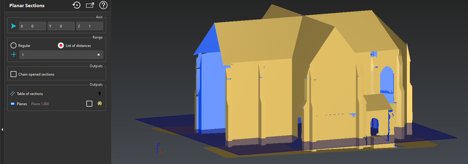 Figure 8: Horizontal section over the model.
Click OK, Exit to validate the results.
Polylines have been created and inserted in Planar Sections.
You can then export these polylines as DXF for example. The surface model can be exported as DXF as well through Export \ Export project in DXF file.
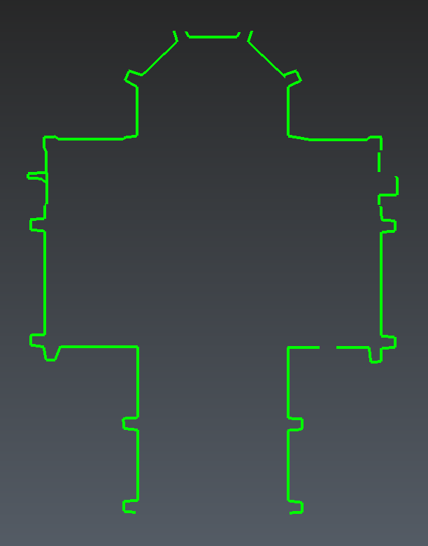 Figure 9: 2D plan of the church.