Loading a 3DR file
Several options are available in order to open a 3dr file:
Double-click on the file in your Windows explorer.
Launch the software and run the command Open.
Launch the software and then drag the .3dr file from your Windows explorer to the software.
For this exercise, open the EnterPoints.3dr file.
Drag and drop as well as double-click is also possible for file formats which are known by the software.
Changing the view
The following exercise will guide you through the most common ways to modify the view. For more details, refer to the sections located in the general instructions.
Rotating, panning and zooming
The mouse will allow you to manipulate the view. Press O to switch to orbit ortho camera mode.
To rotate the view, left click on the middle of the scene and move the mouse while keeping the right button pressed.
If an object is behind your cursor, the corresponding point on the object will be the rotation point (also called picking point).
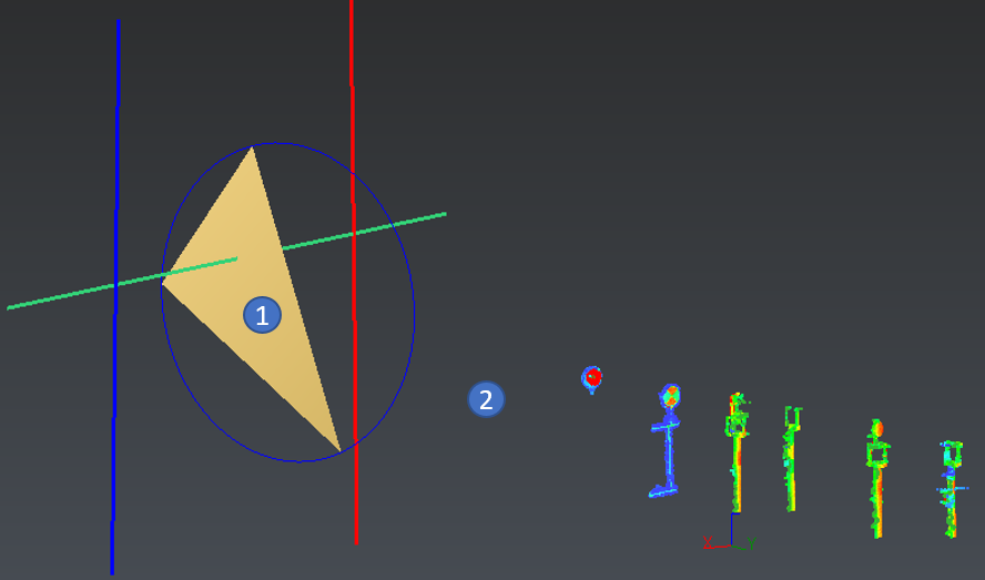
→ Try to rotate the view with the mouse over the triangle (position 1 in the image below).
If no object is behind the mouse, a point in the middle of all visible objects will be used as rotation point.
→ Try to rotate the view with the mouse over an empty area (position 2 in the image below).
Note the Z axis is always parallel to the screen.
 The mouse position will change the rotation conditions
Panning is also done using the mouse, by pressing right button.
Zooming in and out is possible by scrolling the mouse.
→ Scroll with your mouse in the 3D scene.
→ Note that the point behind your mouse is not moving when zooming in or out.
Predefined views
The menu View allows you to quickly change your view to display all objects in the front view:
→ Run the Predefined Views (Front) command.
→ Run the Zoom All command.
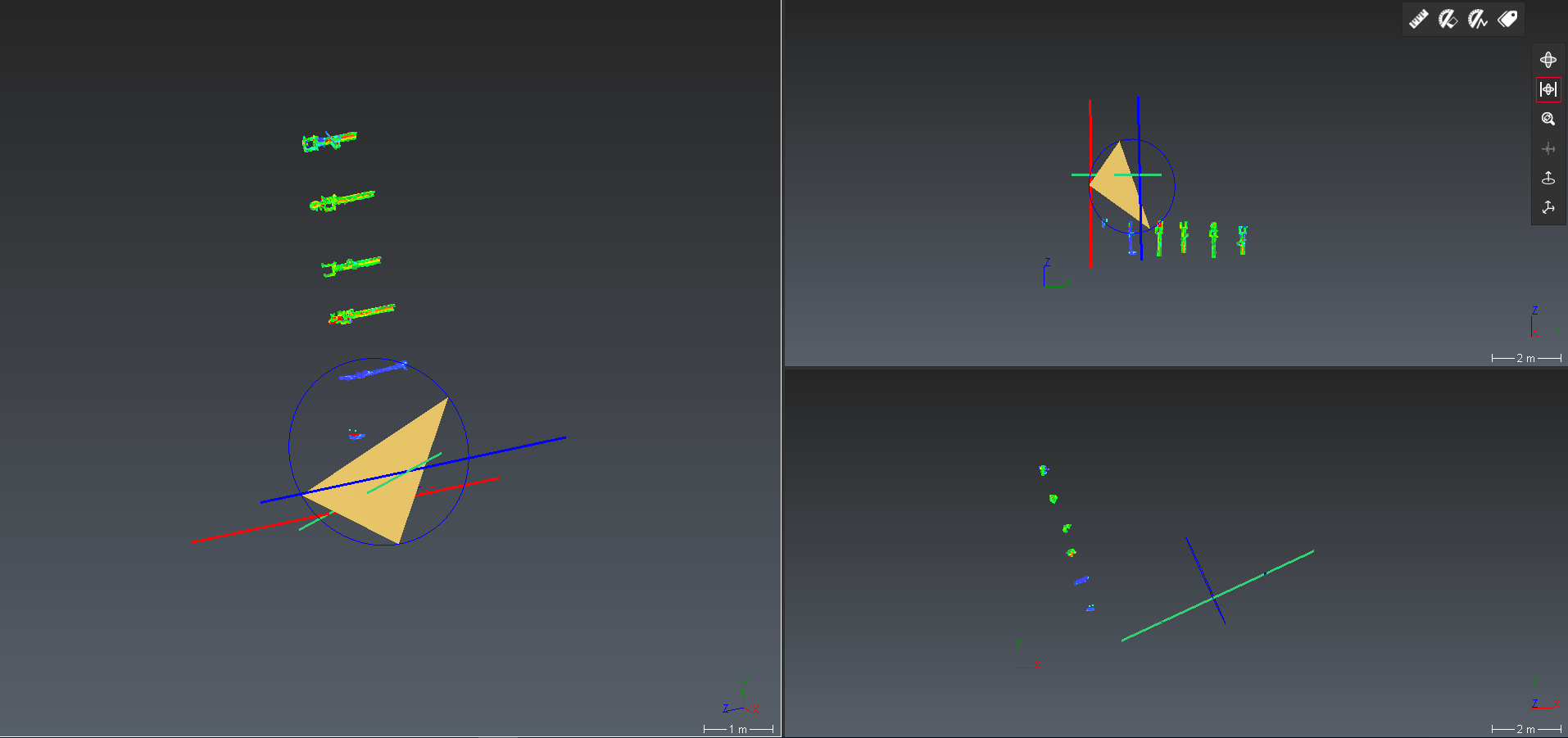
The View menu also contains tools allowing to split the views in up to 8 different views:
→ Click on Split View Vertically
→ Click on the right view so that it becomes the active view.
→ Click on Split View Horizontally.
→ Click on the top right view and then press the X key in order to obtain a Right view.
→ Click on the bottom right view and then press the Z key in order to obtain a Top view.
→ Rotate the left view as you wish.
When several views are displayed, you can also undock them to benefit from multiple displays.
In order to go back to a unique view, run the command Keep Only One View.
 Split views
Keyboard shortcuts
Several keyboard shortcuts dedicated to the view are available in the software:
X: changes the view to YZ view (also called Right view)
Y: changes the view to XZ view (also called Back view)
Z: changes the view to XY view (also called Top view)
A: changes the current zoom so that all displayed objects are in the view
SHIFT+X reverses the view from Right to Left, and of course, the same mechanism is setup to change the view to Front view with SHIFT+Y and to Bottom view with SHIFT+Z. Refer to the dedicated Shortcut keys for more details about all available shortcuts.
Viewsets
The View Set command saves the current view of the 3D scene. A new object is created; you can see it in the tree in Other Objects folder. Thus, you can restore a view by clicking on the corresponding magnifying glass.
Some viewsets have been created in samples and practical exercises. They may be suitable to help you localize specific zones, effects, etc. You could also click on Default Viewset to return to the starting view.
Orthographic/Perspective
The view can be switched between orthographic and perspective by using the tool bar on the right or shortcuts:
 The tool bar contains buttons allowing to switch from orthographic to perspective
Perspective view can be very useful for looking inside objects. An alternative to perspective view is activating a clipping plane.
More information are available in the dedicated page: Perspective and orthographic view.
Limit plane
A limit plane is a visualization tool which helps to see inside an object without modifying it. Consider a limit plane as an infinite plane; everything on one side of the plane is hidden (clipped) and the other side remains visible.
A horizontal limit plane has been created.
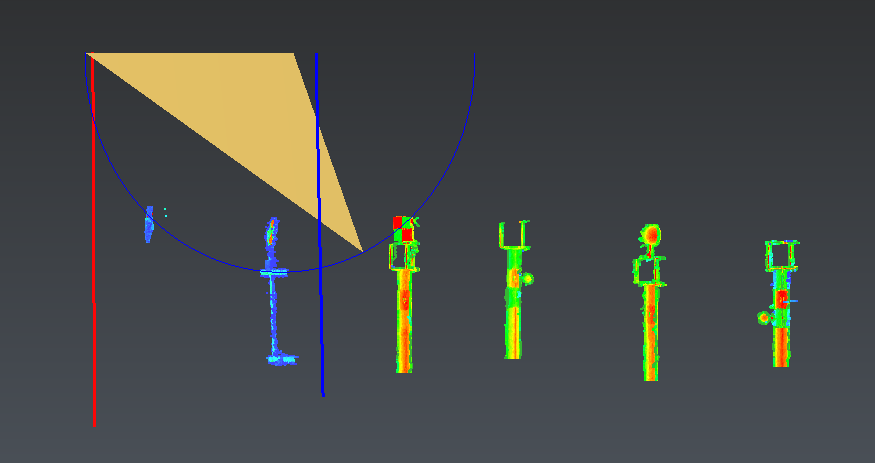 Horizontal clipping plane
In the tree, you can hide (or display) and switch off (or on)
  the limit plane.
Press CTRL+SPACE to edit the limit plane with the mouse (drag and drop, CTRL+SCROLL). Press a second time CTRL+SPACE to exit the limit plane edition mode.
Selecting objects
The way of using the software is to select the data that you want to work with, for example select the cloud(s) to mesh...etc. By default, an object is displayed in purple in the 3D scene when it is selected and highlighted in the tree. You can either select an object in the tree or directly in the 3D scene.
In the tree
The selection of elements in the tree is very similar to the way you can make selections of files and folders in your Windows explorer:
Select only one element one after the other by clicking on it
Select several consecutive elements using the SHIFT key
Select several non-consecutive elements using the CTRL key
→ Try selecting the clouds numbered 1 to 6 in the tree using the SHIFT key.
→ Add to the selection the "Blue segment" polyline using the CTRL key.
→ Remove to the selection the "Target 4 - Checkered pattern" cloud using the CTRL key.
In the 3D Scene
Objects can also be selected directly from the 3D scene:
Refer to the dedicated page Navigation and selection for the difference between rectangles created from left to right or right to left.
→ Press the X key and then on the A key to display all visible objects in front view.
→ Draw a rectangle like in the 1st image below from left to right. The result of the selection should be similar to the 2nd image below
→ Press CTRL and LEFT click on the triangle in order to remove the triangle from the selection. The result of the selection should be similar to the 3rd image below
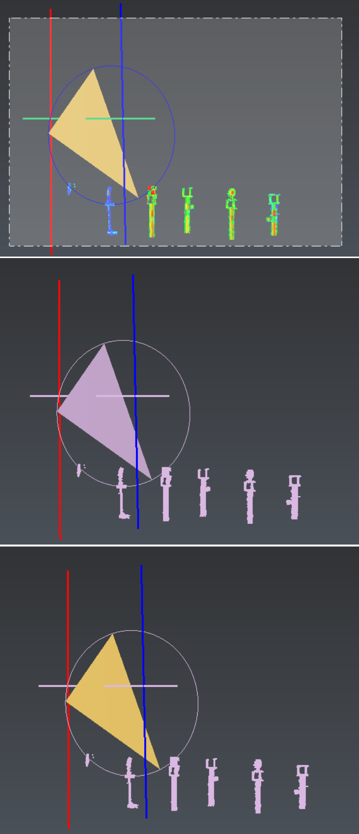 Rectangle selection in the 3D scene
Select all visible elements using the CTRL+A keyboard shortcut and deselect all elements by using ESC key.
Editing an object
Showing or hiding an object
An object can be shown (or hidden) in two ways:
With the contextual menu: select the object to show (using the above procedure), right click with your mouse to show the contextual menu and press on Show (or Hide)
With the tree: click on the bulb icon (which is either on or off) in order to switch between shown and hidden status
→ Hide the triangle by clicking on the lamp icon (which is "on" when the document opens).
→ Select several objects (either in the tree or in the 3D scene) and try hiding or showing them using the lamp icon on the tree or the contextual menu.
Renaming
At any time, you have the possibility to change the name of an object; to do so, you have 3 possibilities:
With the contextual menu: select the object you want to change the name, right click with your mouse to show the contextual menu and press Rename
In the tree, left click twice (slowly, to avoid double-click) on the element you want to rename
Select the element you want to rename and press F2
→ Rename the Circle to "Circle 1"
Moving an object from one folder to another
Regular commands (such as cut, copy, paste, delete...) are available in the contextual menu or in the menu Home. These commands allow to cut an object from one folder and paste it in another folder. Another workflow for moving the objects is to use the drag and drop functionality of the tree which is much quicker than the regular Cut/Paste.
→ Drag and drop the "Circle 1" from the "Geometric Group" to the "Contour Group"
Undo-Redo
Every action you will do in the software can be undone - and then redone if needed. Undo and Redo can be applied using the dedicated Undo and Redo menus or using the keyboard shortcuts: CTRL+Z and CTRL+Y.
→ Select the circle and hit DEL to delete it. See that it moves into the Recycle bin folder and is now hidden.
→ Press CTRL+Z and see that the circle is back to the "Contour Group".
→ Press CTRL+Z again and see that the circle goes back to the "Geometric Group".
→ Press CTRL+Z again and see that the name of the Circle is back to original.
Recycle bin
A deleted element goes into the Recycle bin.
At any time, an object in the recycle bin can be restored in its original folder.
Changing the representation and the color
Most objects can be displayed using different representations (see Object representations for more details). Meshes, for example, can be displayed in: Smooth, Flat, Wire, Smooth+Wire, Flat+Wire, Textured, Real Color or Inspection. Some representations are only available if the information is available: if the mesh contains no texture information, this representation is not proposed. Changing these representations can be done in two ways:
With the contextual menu: after right clicking on a selected objet, go in sub-menu Representation
With the tree: left click on the colored disk
→ Select the triangle and change the representation from "Smooth" to "Smooth+Wire"
In the software, a single color is applied to objects in the representation that do not override colors. Inspection representation, for example, overrides the color. You have 2 ways to change the color of an object:
With the contextual menu: select the object you want to change the color, right click with your mouse to show the contextual menu and go in sub-menu Color
With the tree: left click on the colored disk and change the color
→ In the tree, change the representation of the cloud named "Target 2 - Spherical diam 145mm" to "Smooth"
→ Then, change the color of the same cloud to blue
The different objects
When working in the software, you will certainly create different types of objects: clouds and meshes of course but also polylines, geometries (such as lines or circles), coordinates systems, view sets... The tree view of the document allows you to easily identify the type of objects as a specific icon is dedicated to each object. Depending on the type of objects, different information is available within its properties. You can view object's properties using the command Properties in the contextual menu, or simply by keeping the mouse up to an object in the tree view.
When using the contextual menu, you can display properties of several objects at once if several objects are selected.