Exercise: Draw a longitudinal profile
In the surveying field, it is common to draw ground sections following an axis. This can be achieved using the command Unroll along Axis.
Open the file
Open the file TextureParam&CameraPath.3dr. It contains a mesh and a polyline. This file is going to be used through this whole exercise.
Project the axis onto the ground
To make quotations later, we first need to create a reference plane. Launch the command Draw Plane and define a horizontal plane (Fixed normal: X=0; Y=0; Z=1). Set the Fixed center by clicking one point on the mesh, then modify its Z coordinate to 400 for instance. The plane Width and Length can be set to 1000m in this example. Lock Main axis to complete plane definition. Click OK, Exit.
Now, we are going to project the polyline called Camera path onto the mesh CliffTextured and onto the plane.
Select the polyline and launch Projection. Click on the mesh and define a vertical projection direction. Check also Both sides and Follow the mesh shape by checking the option Add points to better follow the shape. Click Preview and OK, Exit.
Repeat the same workflow to project the polyline called Projected Camera path onto the plane. Thus, you will create two polylines with the same number of vertices. This will help you creating quotations.
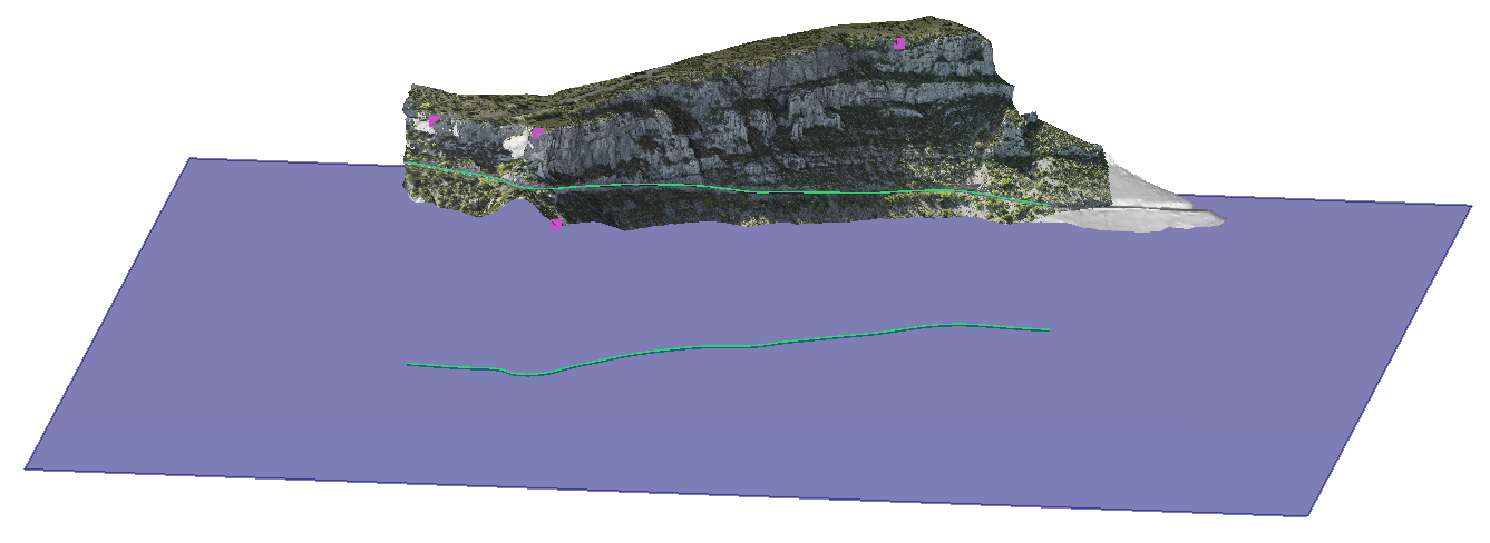 Fig.1: projected polylines
Unroll the polylines
Select both polylines and launch the command Unroll along Axis. Then, you have to choose the polyline which will be used as parameter for unrolling (in other words, the axis). Here, both stand for the axis. Click Preview and OK. Show only the polylines which have been added to the folder Unroll along axis. Press Shift+Y to display the profile from the correct direction.
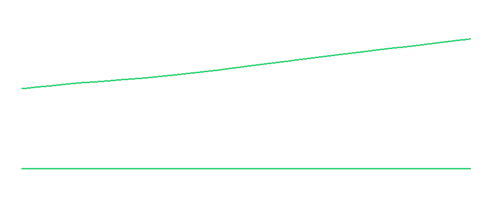 Fig.2: unrolled polylines
Add quotations
Select both polylines starting with the upper profile and launch an inspection between sections (vs Section). Here, you can make a Point to Point comparison. That is why we have created two polylines with the same number of points. Choose to color the upper profile.
Now, click on Edit color in order to check show quotation, to modify the number of decimals... Note the quotations stand for the heights above the reference plane (Z=400).
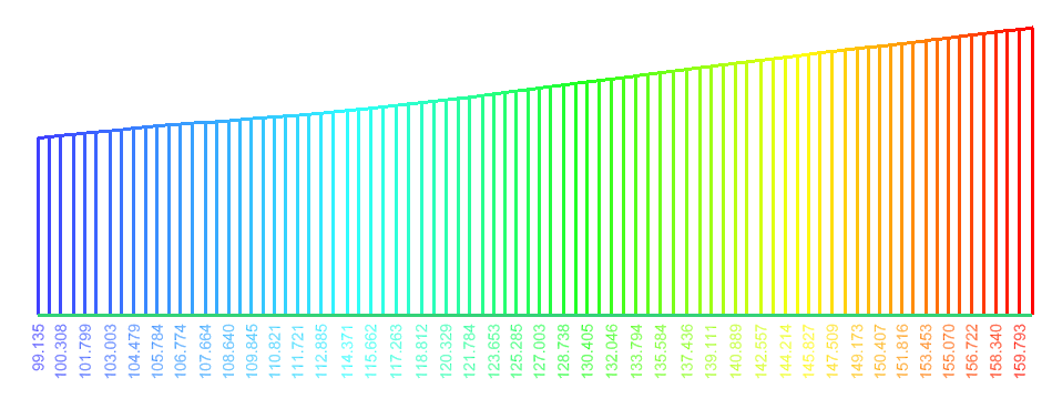 Fig.3: longitudinal profile