Exercise: Improve polylines
Open the file SectionsBuildingPlan.3dr.
Use the planar section previously created on the point cloud. First, you can try the tools seen previously (Cutting and Chaining) on some polylines. Then, we are going to see further processing to improve the polylines. You can look at the polyline Final Building Contour to see an example of a result that you could achieve.
Simplify / Resample a polyline
A polyline can be simplified in order to reduce its noise or to recreate right angles.
Select a small noisy polyline (for example RightAngles) and go to Resample Polyline. Set the number of points of the resampled polyline. If you want a straight line, enter 2. The option Optimize vertices position will compute a polyline going through the noise in order to reduce the standard deviation error. This tool can also be used to recreate the right angles on a polyline.
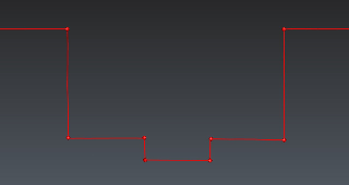
You can try it on the polyline called RightAngles:
Define number of vertices to 6
Check Optimize vertices position
Check Make right angles and set the value to 10°
See the result in the picture below.
 Resample a polyline and make right angles
The standard deviation and the maximum distance between a point and the new polyline are displayed at the bottom of the dialog box. The option Optimize number of vertices allows you to constrain the polyline reduction to be lower than a particular deviation. This threshold can be automatically set up by clicking on the button Compute value.
Smoothing
To reduce the noise in a polyline, you can also select the polyline LineToChain6 and go to Smooth Polyline. Three types of smoothing are available. The smoothing intensity represents the number of iterations of the process.
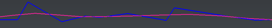
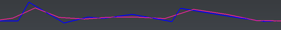
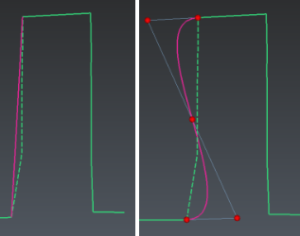
See the pictures below to compare the hard and soft smooth used on the same polyline with the same intensity. The original polyline is in blue and the smoothed polyline in pink. Hard smooth creates a smoother polyline whereas soft smooth tries to keep the general shape of the polyline. With type Bspline, points are resampled, so that they are regularly spaced on the polyline.
As another example, if a polyline representing a rough circle is smoothed with hard smooth; it will tend to a smaller circle. With soft smooth, the radius of the circle will be approximately preserved.
With hard and soft smooth, it is also possible to control the deviation error by entering the maximum deviation authorized between the smoothed line and the original.
 Hard smoothing (LineToChain6)
 Soft smoothing (LineToChain6)
Stretching
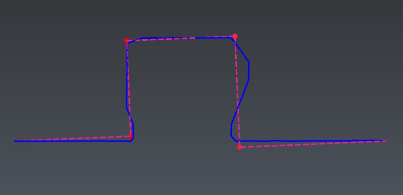
Select the Final Building Contour polyline and go to Stretch Polyline.
Two control points are automatically displayed at the extremities of the polyline.
You can add intermediate control points by clicking specific points on the polyline in the 3D scene (on the right angles, for example).
 Stretching
Stretch a polyline with several control points
The polyline automatically changes when you move a control point. You can change the Stretching type by turning on and off Preserve curvature to have either curvature continuity or sharp angles around the control point.
At any time, you can:
Add a control point by clicking on the polyline where you want the new point.
Press DELETE to delete the selected control points that are not on the extremity.
Activate the option Snap points to other lines to be able to link two polylines by moving a control point from one polyline on the other. When the control point is green, it means that the polylines are connected.
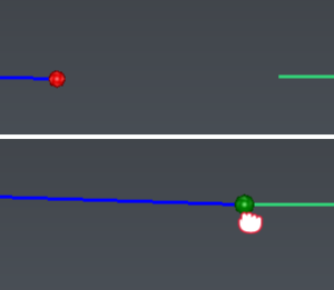 Snap points while stretching
Offset
You can select your final contour or show the object Final Building Contour and go to Offset to create the contour of the external walls. Choose the direction for the offset and set the distance. Here we can compute an offset of 0.3m in the best plane of the contour. The side of the offset can be reversed if necessary with the ![]() button available in Distance field. You can look at the polyline Final Offset contour to see the result.
button available in Distance field. You can look at the polyline Final Offset contour to see the result.
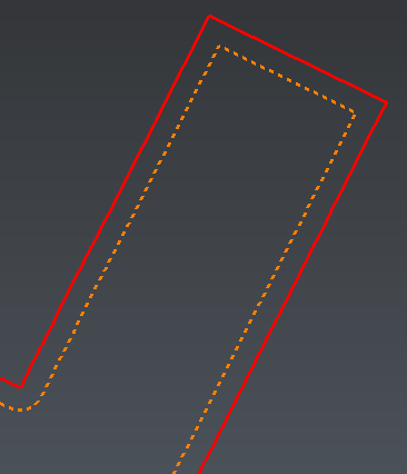 Offset a polyline
Replace a portion
You can replace a portion of a polyline with a segment or a 3D editable curve.
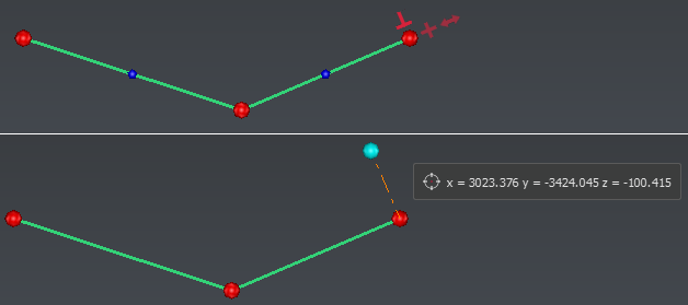
Select the polyline LineToChain1. Launch the command Replace a Portion. Click two points to define the portion that you want to replace by a straight line or a curve (press Enter to validate)
 Replace a Portion
Manual Edition
You can edit a polyline manually using Edit Polyline. For instance, you can:
remove one or move vertices,
insert a vertex,
extend or shorten end segments.
 Edit Polyline
Learn how to create 2d building plans: continue with the practical exercise Create building plans.