Reverse Engineering of a Pelton Wheel - Part One: Alignment
Introduction
Reverse engineering is the creation of CAD surfaces from scan data.
In most cases, a scanner provides the point clouds used to create a 3D mesh. Then, CAD surfaces can be computed from the 3D mesh and a polyline network. CAD surfaces can be exported in IGES or STEP format and further used in other software for Computer Aided Manufacturing (CAM), Finite Element Analysis (FEA) or for comparison and inspection.
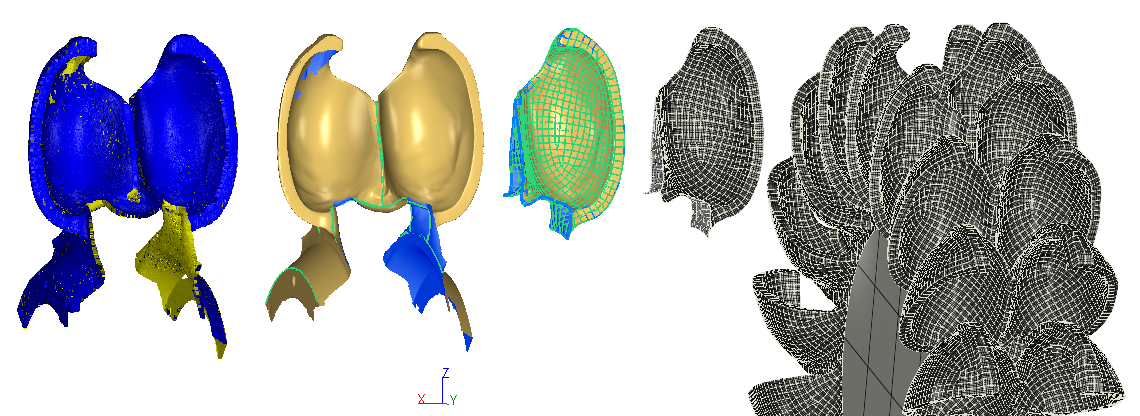
This exercise is part of full workflow that shows how to convert a point cloud into a CAD model. The steps below give a global description of the full process:
Align the part thanks to the extraction of geometric features on a mesh created from the point cloud - this is the part covered in this exercise
Clean the mesh so that it can be replicated by symmetry and rotation
Create an automatic network of polylines and edit this network in the required areas to create the surface
Exercise overview
As shown in the figure below, the coordinate system in which the point cloud was measured was a default one where the Z, Y or X axis do not correspond to anything in the part.
This exercise will show how to align:
The X axis so that it corresponds to the rotation axis of the wheel,
The Y axis so that it is perpendicular to the front plane of the wheel
The origin so that it corresponds to the rotation axis in the middle of the blade
To do so, the following steps are required:
Mesh the point cloud
Extract the X axis on the side of the wheel
Extract the rotation axis
Calculate the middle plane
Compute the origin
Extract the Y axis in front of the blade
Apply the alignment
The file used in this tutorial in PeltonWheel_Reverse_1-Alignment.3dr
The file can be downloaded on Cyclone 3DR - Downloads page.
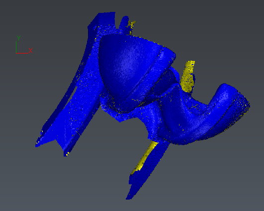 Top view of the point cloud before alignment
Meshing the point cloud
Select the point cloud and launch the 3D Mesh command.
Choose the 2 steps meshing strategy with an average distance of 20 mm. A default value of approximately 60 mm for hole detection is proposed.
Hit OK to create a rough mesh which contains the right topology and continue with the second step of the process which will refine the mesh.
In this refine step, select the following parameters:
Select the Refining method as Refine Mesh from Cloud Interpolation
Select the Mesh generation method as Refine with deviation error
Default parameters for Deviation error, Maximum number of triangles and Minimum triangle size are calculated based on the rough mesh. These apply well here so no need to modify them.
Check the Distance parameter and keep the default value so that sparse point do not affect the results
Uncheck the options to apply a local reorganization
Uncheck the options to filter based on the angle on scanning direction
Finally, choose the option to refine the free border
 Step 1 meshing to get a smoothed and accurate mesh from the point cloud
 Step 2 meshing to get a smoothed and accurate mesh from the point cloud
From this mesh, a lot of geometric data can be extracted for defining a precise alignment.
Extracting the X axis
The X axis that we want to define is facing laterally to the blade.
Launch the Region Grow Plane tool and pick a point on the side of the wheel (the one which is less damaged!).
As we need only the plane information, you can leave unchecked 'Extracted Points' and 'Label' in order to keep only the 'Plane' object (the center point and the normal direction must be unlocked).
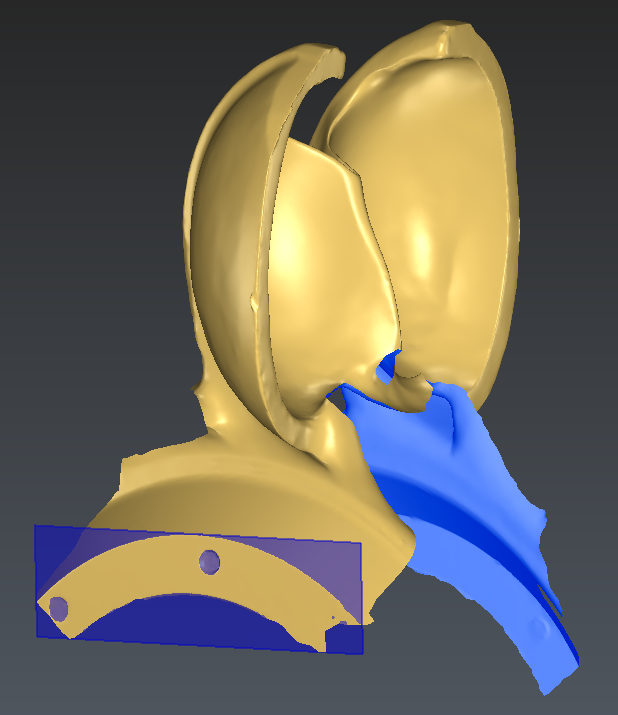 Plane extracted on the side of the wheel
Extracting the rotation axis
The rotation axis will be extracted on the curved circular area that we can see on the mesh, at the end of this plane.
To extract the circle, we will first extract the feature line:
Select the mesh and launch the Single Breaking Line command
Choose the option Only concave or only convex
Pick 2 points at the begin and end of the curved area as shown below with the 2 red balls
 Extraction of the feature line
A polyline is created between these 2 red balls that follow the curved area of the mesh, i.e. the circle that we are looking for.
We will now create the axis that we are looking for by best fitting a circle on this polyline:
Select the polyline and launch the Best Circle command
Force the normal to be perpendicular to the previously measured plane:
Lock the normal by clicking on the corresponding lock icon
Select the normal with the option Direction of a component
Pick the plane previously created
Keep only the circle as outputs
Hit OK
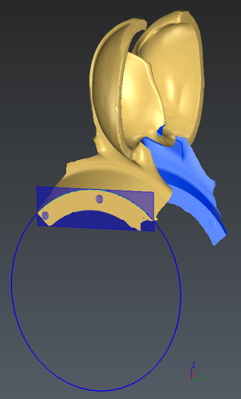 The circle best fitting the extracted feature line and aligned with the side plane
Calculate the middle plane
The middle plane that we are looking for is in the middle of the wheel and parallel to the side plane: its mathematical definition is the best symmetry plane that is parallel to the side plane.
In order to calculate a symmetric plane, an initial one must be created. This initial plane should be parallel to the side plane and close to the middle.
The following process is therefore required:
Duplicate the side plane with a Copy and Paste operation and hide the initial side plane.
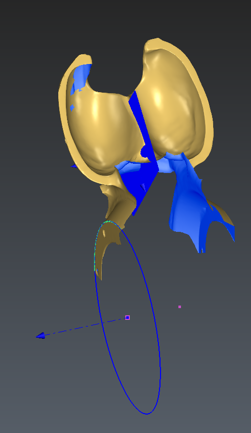
Edit the newly created plane to approximate the middle plane
Select the plane and launch Edit Plane or double click or use the contextual menu (right click) on the duplicated plane
Drag the plane using preferably the green plane of the manipulator so that it is close to the expected result
Hit OK
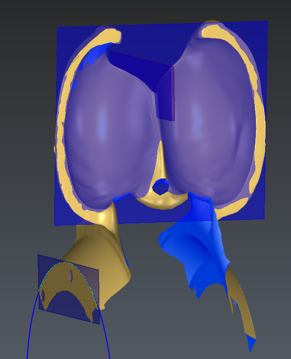
Calculate the best symmetry plane
Select the approximated plane and the mesh
Launch the Best Symmetry Plane command
Define constraints and choose the option to Disable rotations (Only parallel plane)
Hit OK
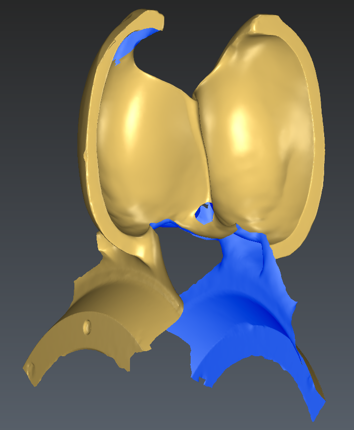
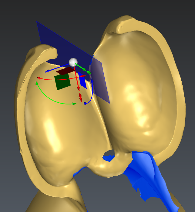 Translating the plane to an approximate position
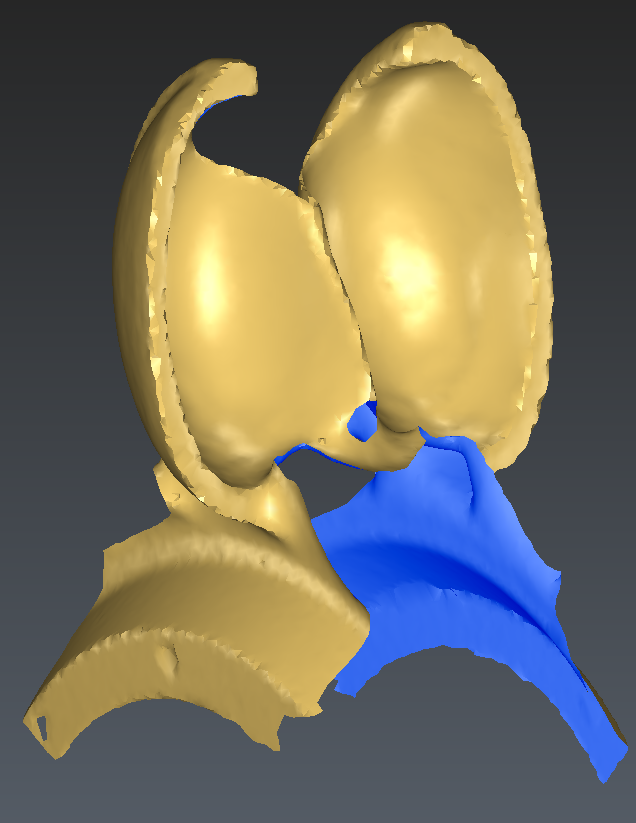
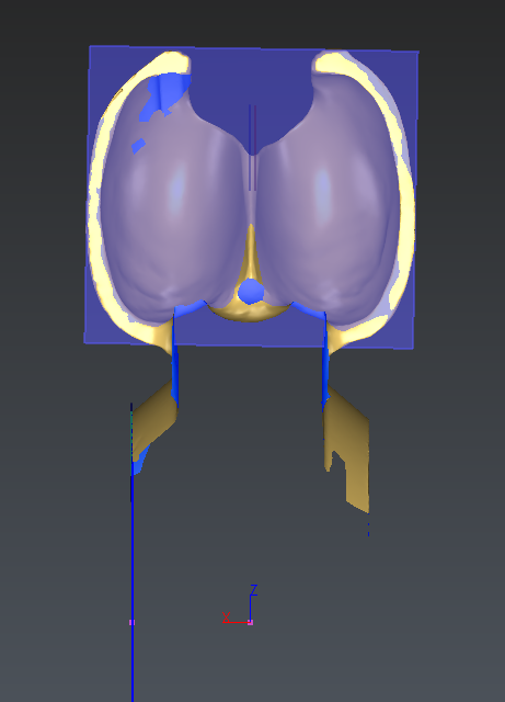
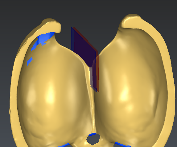 Best symmetric plane calculated (in blue) from the approximated one (in red)
Computing the origin
The origin of the alignment that we are looking for is actually the center of the circle previously calculated projected onto the symmetry plane.
The steps to create the origin are the following ones:
Create the point at the middle of the circle using the command Point and the option Middle / Center or use other option to select the existing center if displayed by default.
Select the point that was just created and the Symmetry plane and launch the Projection command
Choose the Shortest distance option and hit OK, Exit
You can rename the projected point to Origin.
 Projected point on the symmetry plane
Extracting the Y axis in front of the blade
The Y axis that we are looking for is facing in front of the blade.
The procedure to create it is as follow:
Launch the Region Grow Plane command
Hit 2 points (or more if needed) in front of the blade of both sides and validate with OK, Exit (if necessary adjust the extraction tolerance to 5or 10 mm)
 Plane extracted in front of the blade
Applying the alignment onto the mesh
Every component previously created now allow to apply an alignment onto our data.
Select all the data and launch the Geometric Registration command:
The source point of the Origin will be the point named Origin
The main axis is X and is defined on the side plane
The second axis is Y and is defined as the front plane
Hit OK
 The data is now aligned with X, Y and Z and the origin of the coordinate system is on the revolution axis of the wheel