Reverse Engineering of bowling skittle
Introduction
Reverse engineering process allows to create a 3D model from a real object in order to duplicate or to modify it. It can also be used if the current drawings of the physical object are missing or incomplete. In this case, measurement of free-form surfaces can only be achieved through scanning and point cloud processing as explained in this exercise.
Once the scan is done, we've got a point cloud that can be cleaned (to remove the noise) or segregated. Next step is the mesh creation. This 3D mesh model is ready for fast prototyping, tool path generation, simulation, analysis… But in order to use measured/scanned data (point clouds) in modern computer-aided design (CAD), manufacturing (CAM) or engineering (CAE) software, you may need to generate a CAD surface model, such as IGES or STEP file.
Exercise overview
In this exercise, we will see how to convert a point cloud into a CAD model. The process will be as follows:
Align the part thanks to the extraction of the best revolution axis
Mesh the point cloud
Create a network of polylines using Planar Sections and Radial Sections
Create and improve the surfaces
The created part will also be compared to the initial point cloud.
The file used in this tutorial is Skittle.3dr
Align the part
Most of the time, a correct alignment is very important and will help in the reverse engineering workflow.
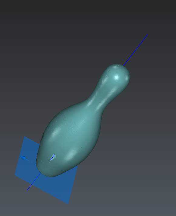
In the case of the skittle, it is interesting to align the part with a Z axis along the revolution axis of the skittle and with the origin of the part being the center of the base circle.
During the scanning session, the table plane was probed and is available in the project as Plane object in the Geometric Group folder. Hit the lamp in the tree view to show this plane in the 3D view.
Best Revolution Axis
The calculation of the best revolution axis requires a first rough axis close to the expected solution (to be used as a starting solution).
Draw manually an approximate axis with Draw Line
Click on Z to correctly orientate the view
Define the position of the center of the line on the top of the skittle: click
 , select the option Point on selection of Define points and hit a point on the top of the skittle, then modify its Z coordinate: set 200.
Set the line Direction to Z
Set the length of the line to 600 mm
Click on OK, Exit
 Define rough axis
This line is a rough axis. To compute the best revolution axis, select Cloud1 and Line and launch Best Revolution Axis. A new line called Line Revolution Axis is created in the tree.
 Best axis revolution with the restored one
Create intersection point for Alignment
To compute the intersection point, select the Plane and the Line Revolution Axis and launch Intersection. Press OK, Exit, a new point called Intersection Plane & Line Revolution Axis is created in the tree.
Rename this point to Origin.
Align the point cloud
Select the entities to move before launching the command. A new dashed line coordinate system is automatically drawn in the 3D scene. By default, the new coordinate system is initialized at the same place as the existing coordinate system but its position will be updated in real time according to the parameters you enter in the dialog box.
Select Cloud1, the point Origin, the Line Revolution Axis and the Plane. Launch Geometric Registration
Define the departure point (source) with the button
 through a click on the intersection point (with the mode Vertex / End of the Define points)
Define the new Z as the revolution axis: click the Z radio button of the main axis direction. Define the direction by clicking
 and use the option "Direction on a component", then click on the revolution axis.
Check that the new Z axis, in dashed line, is pointing upward. If it is not the case, revert the main axis direction
Validate with OK
 Align the point cloud
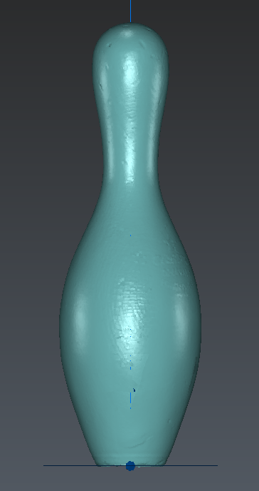
The point cloud is now correctly oriented: the origin of the coordinate system is the center of the base circle and Z is now the best revolution axis.
Edit the probed plane
Note that the normal of the aligned probed plane was exactly the Z axis. This is not the case anymore as the revolution axis was not exactly parallel to the Z axis.
Select the plane and launch the command Edit Plane to modify the plane. The center must be exactly (0, 0, 0) and its normal set to (0, 0, 1).
You can hide the Plane, the axis and the Origin point for the next steps.
Mesh the point cloud
Create a rough mesh
Select the cloud Cloud1 and launch the 3D Mesh command:
Use the option Meshing in two steps
Set the Average distance between points to 10 mm
As we want to avoid holes, but as there are no points on the bottom of the skittle, choose the option Try to keep only the external border
Click Preview
You can change the representation of the mesh to Flat + Wire with the contextual menu in the 3D scene. For such a smoothed shape, there is no need to create a huge amount of triangles as this mesh is only a rough mesh in which details will be added in the next step.
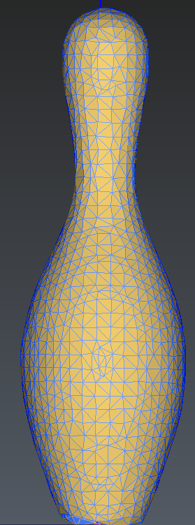 3D Mesh step 1
Refine the mesh
Click OK to continue with the second step which will refine the mesh (add details in curved areas):
Use the method Refine Mesh From Cloud Interpolation
Select the option Refine with deviation error
Set the Deviation error to 0.1 mm
Set the Maxi number of triangles to 10 000 and the Minimum triangle size to 0.2 mm
Activate the Local reorganization option
Choose No free border modification
Hit Preview
At any time, you can change some values and options to understand their influence.
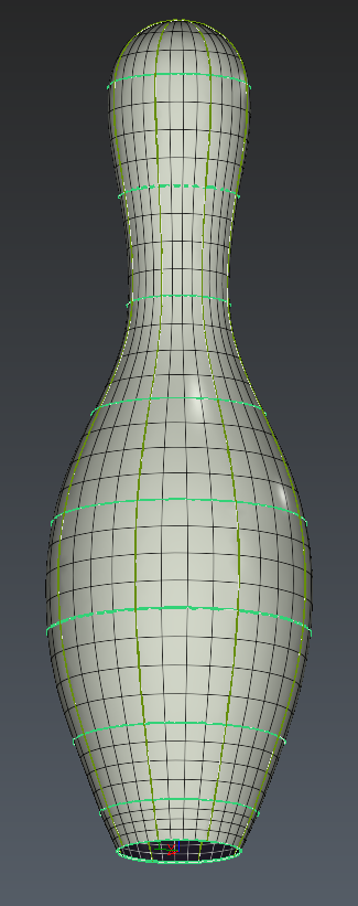
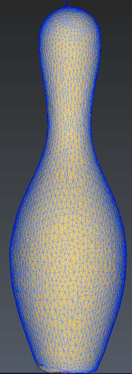 Step 2: Refine the 3D Mesh
Use the Flat + Wire representation to see how triangles are changing when you click to preview.
Validate by OK.
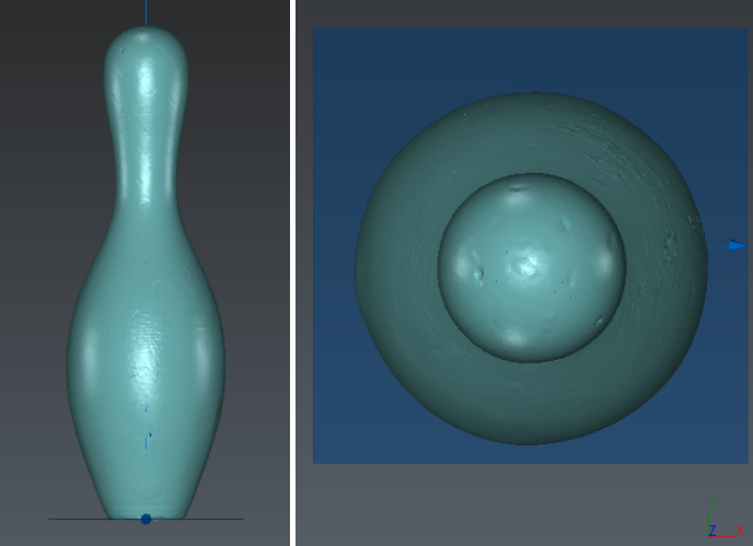
Refine borders of the bottom mesh
The final step for the meshing is to improve the borders at the bottom of the mesh. We will create a circle with known dimensions. Thanks to the alignment, the circle center and orientation are easy to set.
Launch the command Draw Circle
Click 3 points at the bottom of the skittle
Set the position of the center of the circle to the origin: enter 0 in all three text fields
Set the direction to Z by clicking on

then click on Z
Fix the radius of the circle to 28 mm
Click on OK, Exit to validate
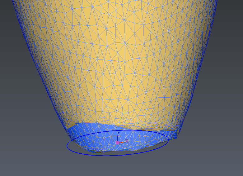 Draw and edit the circle
Now select the mesh Cloud1 as well as the circle Circle then launch the command Define Borders:
Define the Cleaning distance to 15 mm
Click on Preview to visualize the result. You can better visualize the results by hiding the input mesh.
Validate by OK
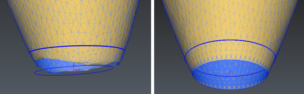 Create a clean border
Now, the mesh is ready for the process leading to the creation of CAD surfaces! To create patches, we need first to create a network of sections.
The next sections in this exercise explain the workflow.
Create a network of polylines
Radial Sections
Select the mesh Cloud1. Launch the command Radial Sections. This command computes a set of radial sections around an axis. A set of sections is actually a single entity, but you can access each individual section using the command Ungroup Polyline.
Define the parameters: Axis Direction (0 0 1) + Axis Origin (0 0 0)+ 8 sections all over and press Preview. Then validate with OK.
Planar Sections
Select the mesh Cloud1 and launch the command Planar Sections.
Define the parameters: Plane Direction (0 0 1), Regular, Step: 50 mm, All Over and press Preview. Then validate with OK, Exit.
You can add one planar section near the bottom of the skittle to improve the accuracy of the surface patches: start the process again and use the option list of values, define the height of the section with the button
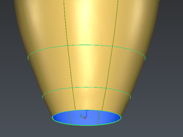
 Planar sections
Extract the contour of the hole
Select the mesh Cloud1 and launch the command Click Holes And Borders.
Hide the bottom circle if necessary (it is not a polyline object) and extract the bottom contour in order to do the subsequent step: the network of curves.
 Extract hole and border
Create CAD surfaces for the body of the skittle
Generate patches
Select the mesh, the radial sections, the planar sections and the contour of the hole. Launch the command Generate Patches.
Note: Outside of CAD surfaces are light grey by default. If the surface is wrongly oriented (dark grey), select the CAD surface and reverse it (right click and Reverse in the contextual menu).
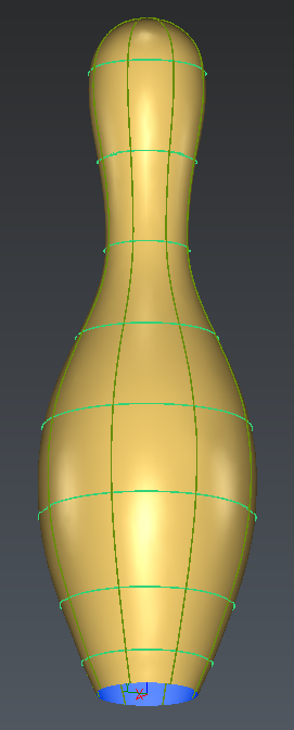
 Patch creation
The next section will explain how to close the bottom of the skittle in order to obtain a solid.
Create the underside face of the skittle
Extract the bottom contour of the CAD surface (and not from the mesh) From CAD Surface (select the created CAD Shape before launching the command) , select it, launch Fill Surface and validate.
Finally select the face Surface from CAD Wire and reverse it using the contextual menu so that it is correctly oriented.
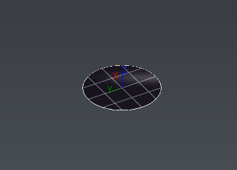
Keep in mind that all the surfaces are tangent but still individual objects.
Sew the surfaces and export to IGES/STEP
Select CAD Surface of the skittle and the CAD surface of the underside
Launch the command Sew Surfaces
Use the parameter 0 mm as the surfaces have perfect connected borders (otherwise it could be helpful to adjust this parameter).
The CAD object is now a solid that can be exported in IGES/STEP (File/Export).
Comparison with the initial cloud
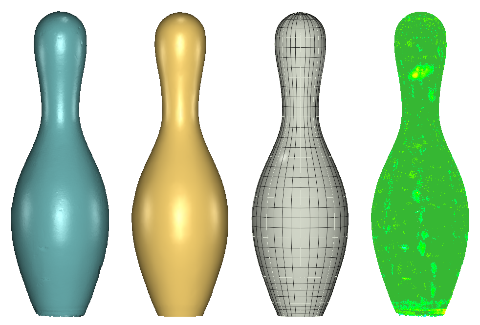
We can check the error of the reverse engineering process with a 3D inspection.
Select the shape and the original Cloud1. Launch the command Cloud vs CAD. Choose to apply the color on the object to project Cloud1 (measured). Do a 3D inspection (do not force a projection direction) and uncheck the Max distance option. Click Preview.
You can change the color scale by clicking on Edit Color, set 0.1 mm and -0.1 mm to the 2 intermediate levels.
From this histogram below, we can see that 88% of the measured points rely within 0.1 mm of the created surface. This value of 0.1 mm can be considered as high if we wanted to create an exact duplicate of the initial part.
However, considering that the part is an old skittle, it contains many defects which we do not want to model here.
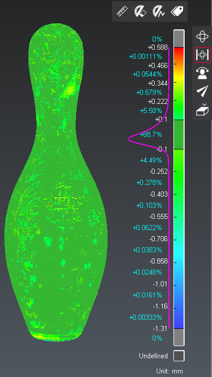 Comparison between the point cloud and the final CAD object