Exercise: Texture a mesh with camera parameters, adjust textures and export
In this exercise, you will:
extract the existing textures.
display their positions.
edit the set of images and extract images.
estimate their poses again to correct them or/and check their external parameters (different for each picture) and internal parameters (different for each camera) to do a very accurate texture mapping.
apply the textures again.
adjust the textures.
export the textured mesh or save the document again (a new folder containing the images will be created).
Open the file and launch the command
Open the file TextureParam&CameraPath.3dr.
Select the mesh “CliffTextured” and go to Extract Texture.
The images become available in the treeview within a set of images (Images Group folder).
Display the position of each image
Press Shift + S or click on the Scan location icon in the graphic scene to display the position of the images through a red sphere.
You can double click on red spheres to go the camera viewpoint and display the corresponding image with the panorama camera mode activated by default. Change the camera mode to hide the image in the graphic scene.
Edit Image Set and isolate the images
Double click on Set of images in the treeview (or Right click and Edit in the contextual menu) to display the content of a set of images.
Use Ctrl A to select all, move the cursor over the list of images and select one arrow to take the selected images and positions out of the list.
Click OK if you want to extract all images and positions.
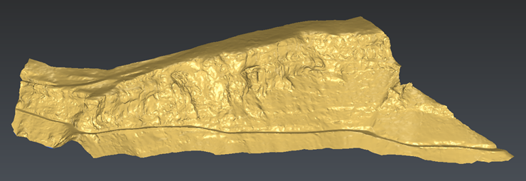 The mesh to texture with camera parameters
Check external and internal parameters
Select an image in the treeview (Images Group), 1029 for instance, and go to the Edit Image. The external and internal parameters are already filled because this image comes from an existing textured mesh.
In most cases, you will have to define these parameters.
External parameters can be computed thanks to Estimate Pose.
Internal parameters can be computed thanks to Calibrate Camera.
The Edit Image dialog box goal is to edit manually these data. Then you can save or load these parameters (excam, incam text files or xml).
Internal parameters are:
The sensor size and the pixel size
The focal length
General tab
The lens misalignment
Principal point of auto-collimation - PPA (offset from the PPS)
Principal point of symmetry - PPS (offset from the CCD center)
Distortion tab
The radial distortion (from k0 to k6)
The tangential distortion (from p1 to p2)
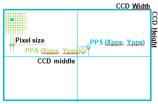 Camera internal parameters
External parameters are:
The camera position
The camera rotations
Learn more: Edit Image
Apply textures
Once all parameters (internal and external) are entered for all textures, show only the mesh MeshToTexture, select it and the three images and go to Standard Texture. Choose to texture Fully visible triangles with Best Projection image choice.
If you observe in detail the result, you should see that some triangles are not textured because they are not visible from any point of view corresponding to the camera positions:
Some parts represent a big surface and can be considered as “normal” zones, in particular on the left part of the picture 1029.
Some parts represent a very small surface (1 or 2 triangles) in the very deep holes of the rock.
You can try other options (At least one visible vertex and Invisible parts) to texture blank areas. Click the Preview button again to see the difference.
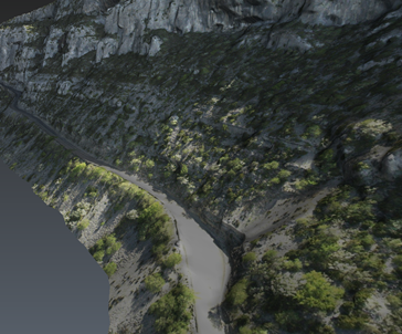 The cliff textured with a perspective view
Adjust textures
By default, when a triangle can be textured by several pictures, a choice is made according to two parameters:
The distance between the camera position and the triangle.
The angle between the camera orientation and the triangle normal.
However, in some cases, you may want to select manually the texture to apply. To do this, show only the textured mesh, select it and go to Adjust Textures.
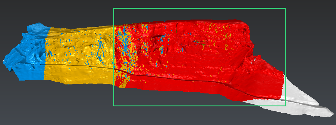
Thanks to the dialog box, you can represent the textures by unique colors or visualize them separately to better visualize where each one is mapped on the mesh. You also have tools to display images in the 3D scene.
In the central toolbar, you have selection tools, filters which are applied to the selection and actions which are going to be done on the next selection. For instance, select the texture 1032 (displayed in red in our example):
Display Colors so as to better understand where textures are currently applied,
Select through to select triangles hidden by others from user viewpoint,
Select No Filter to select triangles hidden by others from camera viewpoint,
Choose Update textures to replace previous applied texture,
Draw a rectangle as shown below
 Adjust Textures dialog box
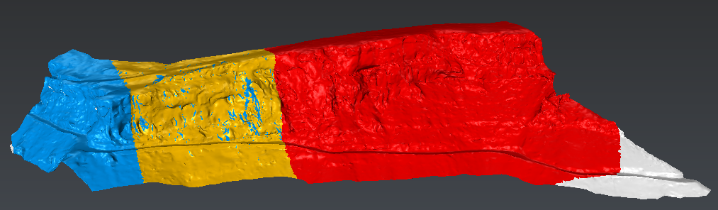 Result of Adjust Textures
The selected area will take the color of the texture 1032.
Then select options Remove Current Texture, and “erase” some triangles on the right. They will become white, means that they will not be textured.
Click OK to validate.
Export a textured mesh
Now that the texture is applied and adjusted, we can export the mesh. You can select it, then go to Export. OBJ, GLB and FBX formats allow the export of textured meshes. Note that some software are not able to handle files with big coordinates, so maybe you will have to translate your mesh near the origin to remove them.
If you save the document or the project (*.3dr), you will create a folder, next to the file, containing these images,