Surface Flatness
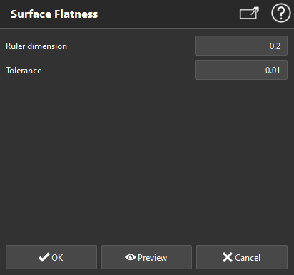
This command allows you to inspect the flatness of a mesh or a point cloud. An inspection value will be associated to each point of the cloud or vertex according to the local flatness.
The algorithm moves a cylinder aligned to the Z axis all along a regular grid covering the object surface. The ruler radius corresponds to the cylinder radius.
For each cylinder position, a best local plane is computed.
Then it compares points inside the cylinder to the local plane so as to evaluate the flatness of the associated area according to a given tolerance.
Select the mesh or the cloud on which you want to analyze the flatness and launch the command.
Tip & Trick: measure the flatness of a wall
You have to create first (and activate) a User Coordinate System with a Z-axis perpendicular to the wall.
Note
You can also launch this command, without selection, to analyze the levelness of planar parts of a cloud or a mesh. See paragraph "Compute the analysis on a planar area extracted from a mesh or a cloud" at the bottom of this page.
|
|
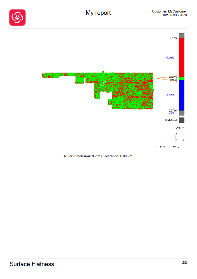
Note The calculated inspection value is local. It means that the flatness calculated for each point only considers its neighbors within a maximum distance of half the ruler dimension. Note A default color map is proposed with 2 thresholds: green for points inside the tolerance, red for points above the tolerance (points are above the ruler) and blue for points below the tolerance (points are below the ruler). |
Create a report
This command automatically creates reporting data ![]() in your document. This object stores your results so as to create a report later.
in your document. This object stores your results so as to create a report later.
From the treeview click on the magnifier icon![]() to launch the report editor (or launch Report Editor). Then, each object
to launch the report editor (or launch Report Editor). Then, each object ![]() stands for a chapter which can be added to your report.
stands for a chapter which can be added to your report.
Refer to Reporting to learn how to customize your report.
A report

