Reverse Engineering of a ship hull
Introduction
The polygonal mesh modeling process generates quality models, made up of hundreds or thousands of triangles. These 3D mesh models are ready for rapid prototyping, tool path generation, simulation, analysis, etc.
In order to use the measured/scanned data (point clouds) in modern computer-aided design (CAD), manufacturing (CAM) or engineering (CAE) software, you may need to generate a CAD-model, such as IGES or STEP, which can be manipulated with those software.
This process is called reverse engineering. This software is a complete solution for the modeling of typical CAD objects, by providing you all the necessary functions for the construction and the processing of BSpline and Nurbs surfaces.
Exercise overview
In this exercise, we will see how to convert a mesh model into a CAD model. The process will be as follows:
Generate a polyline network representing the CAD faces borders using Create Network
Enhance this network to facilitate the patch generation and improve the final result from Edit Network
Generate a shell from the polyline network lying on the hull with Generate Patches
Export the result
When you design your patches, try to make them, as much as possible, rectangular.
A specific attention has to be made on keeping the continuity of the curve network in terms of radius and connections.
While this exercise is mainly focused on editing the polyline network coming from Create Network command, complementary polylines can be inserted into the network to improve the result.
Have a look at the following commands for advanced processing:
Exercise overview
The file used in this tutorial is hull.3dr.
Generating the CAD network
Select the hull mesh and launch Create Network
We want a simple regular grid with a step of 1.5 m covering all the mesh.
Fill those parameters inside the Create Network command:
|
Edge Length |
1.5 |
|
Border management |
Extend to border |
|
Constraint selection |
Uncheck Use constraints |
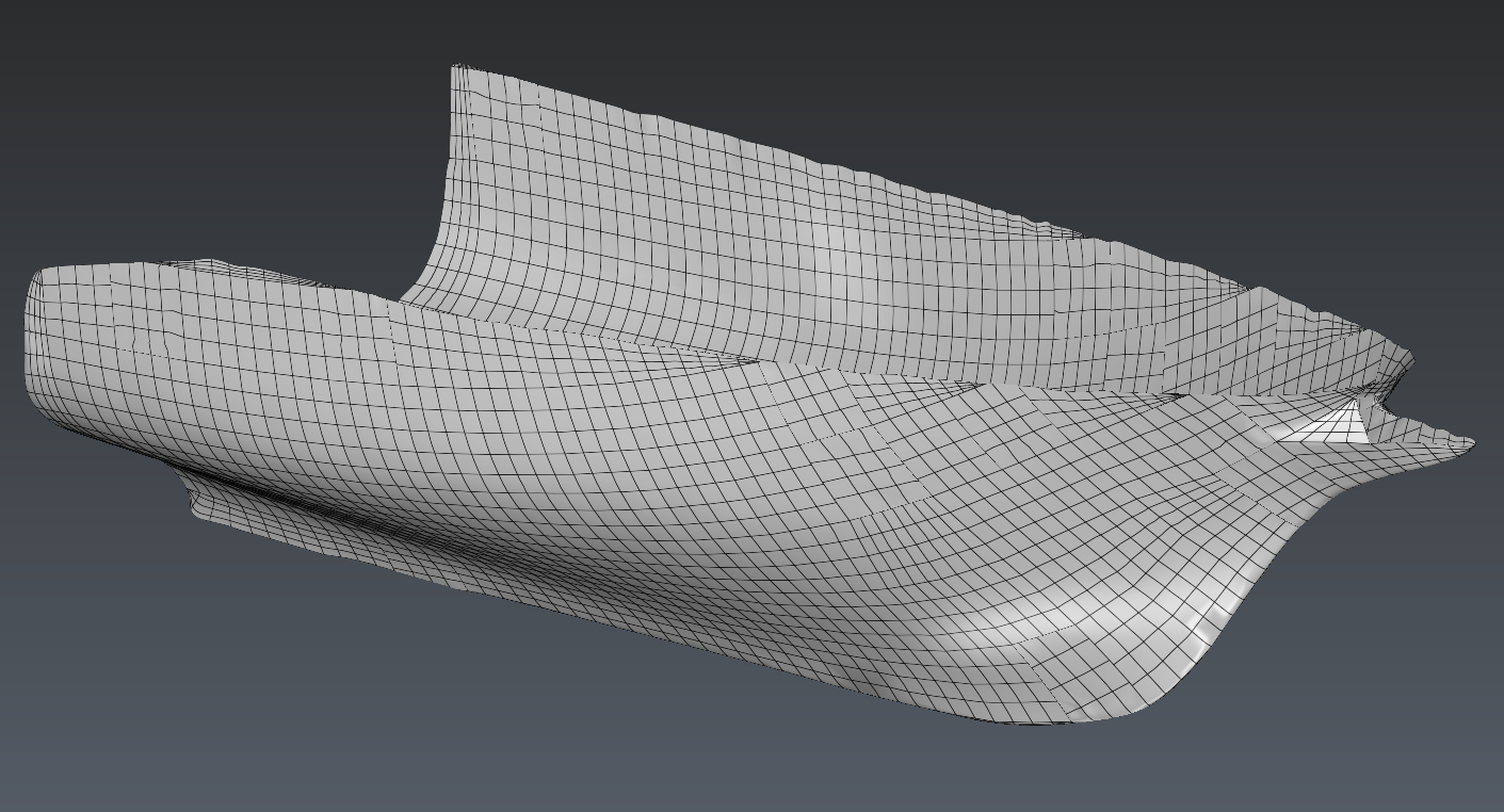
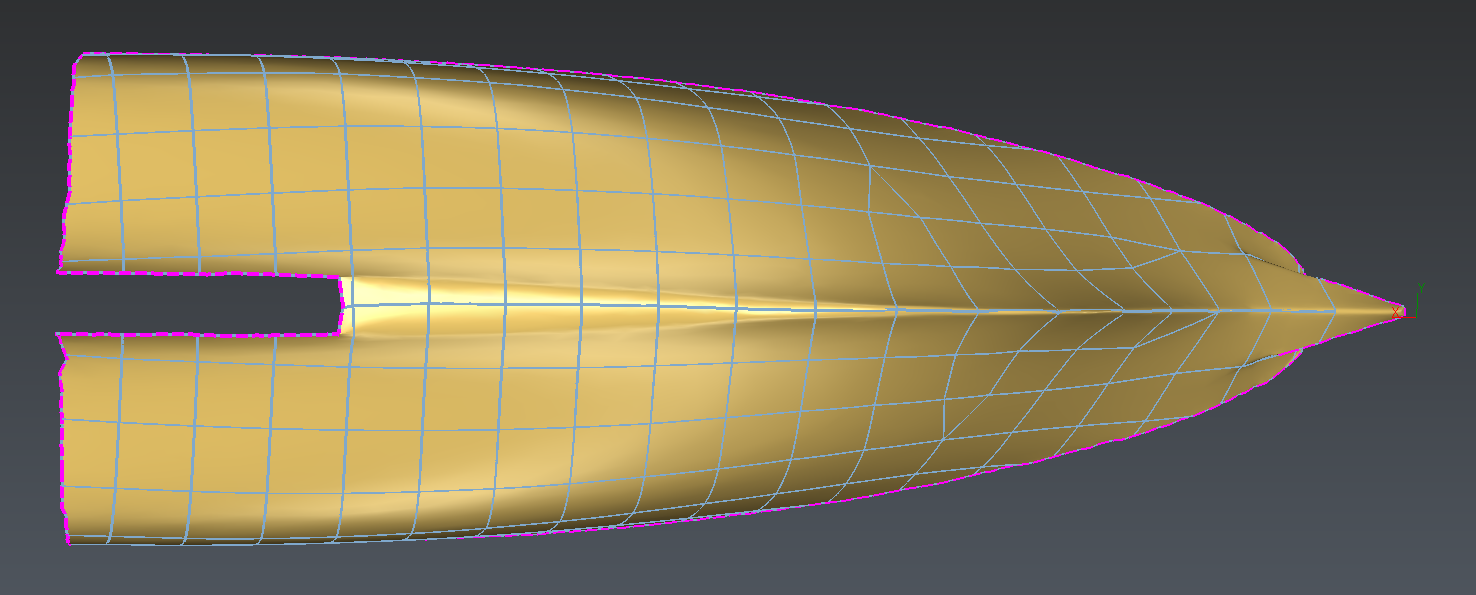 Create network result
Click on OK, the network is outputted in the Contour Group folder.
This network is a good start to generate the patches. However we can notice that some details (such as the bottom of the hull or the bow) are not well covered by the network. If we generate CAD faces now, those details will be omitted and we may lose a lot of details. Using Edit Network command will help us solving those issues.
Enhancing the network
Select the mesh and the polyline network from the previous step then launch Edit Network.
There a few things that we can do to improve the future result:
Removing 3-borders cells
Adding network data in the bottom of the hull
Editing the network cells of the bow
Removing 3-borders cells
Those kind of cells are considered degenerated so it's better to avoid them as much as possible.
Check that the current edition option is Modify Network.
Localize a 3-border cell.
Red nodes indicates nodes connected to more than 4 borders so it's a good indicator to check the network quality.
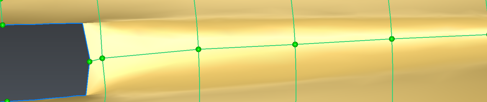
Select an edge and press DEL key. A 5-borders cells appears.
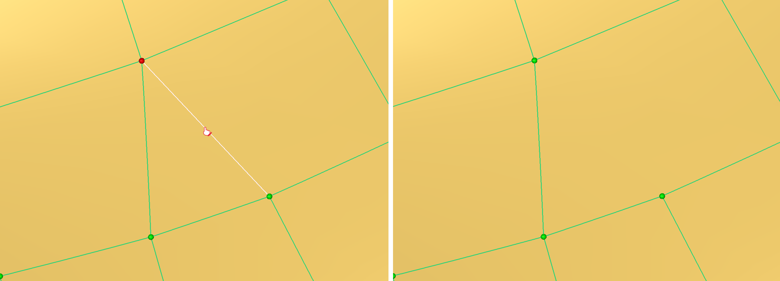 Removing a segment (Select the segment / delete it)
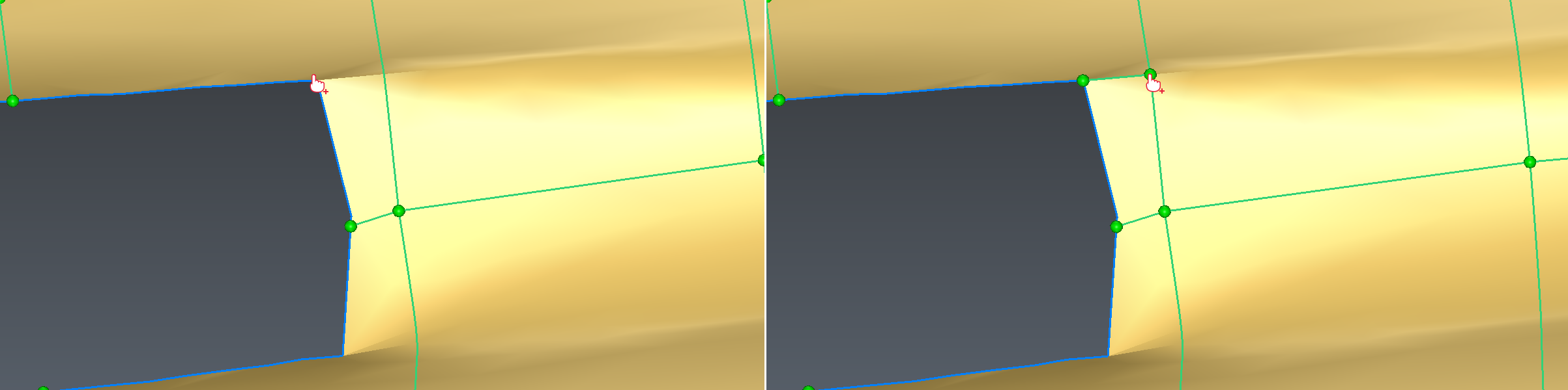
Enable the Create new edge mode
Select the node in the middle bottom of the borders and click on the opposite edge. The 5-borders cell is split in two 4-borders cells.
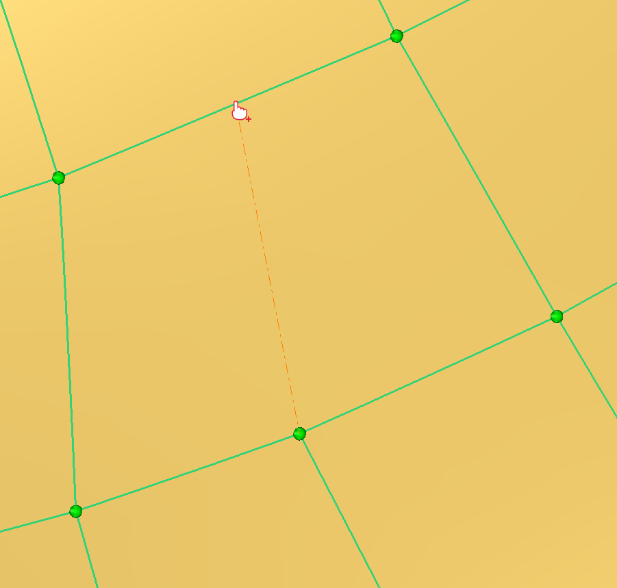 Adding a new segment
The degeneration has now been removed.
Adding network data in the bottom of the hull
This area lacks polylines, if it stays like this we may end up is losing curvature details when the patch will be generated.
 Bottom of the hull lacking network details
We will create new cells in the network.
Enable the Create new egde mode.
Press ALT and click the first extremity on the corner of the external border and the second one on the corresponding existing polyline. A new edge is created.
Now click on the previous created node then press ALT and click on the next polyline by following the full curvature. Again an edge appears.
 Adding new cell
Repeat the process all along the hull bottom.
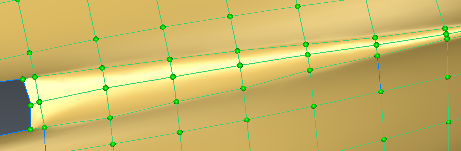 Adding network data in the bottom of the hull
Editing the network cells of the bow
Some parts may require more specific treatments as they are too complex for automatic network generation.
By using the same tools as before, we can enhance the network with new edgethat better follow the shape of the bow.
For example, it is advise to add edge when there's curvature breaks along the shape.
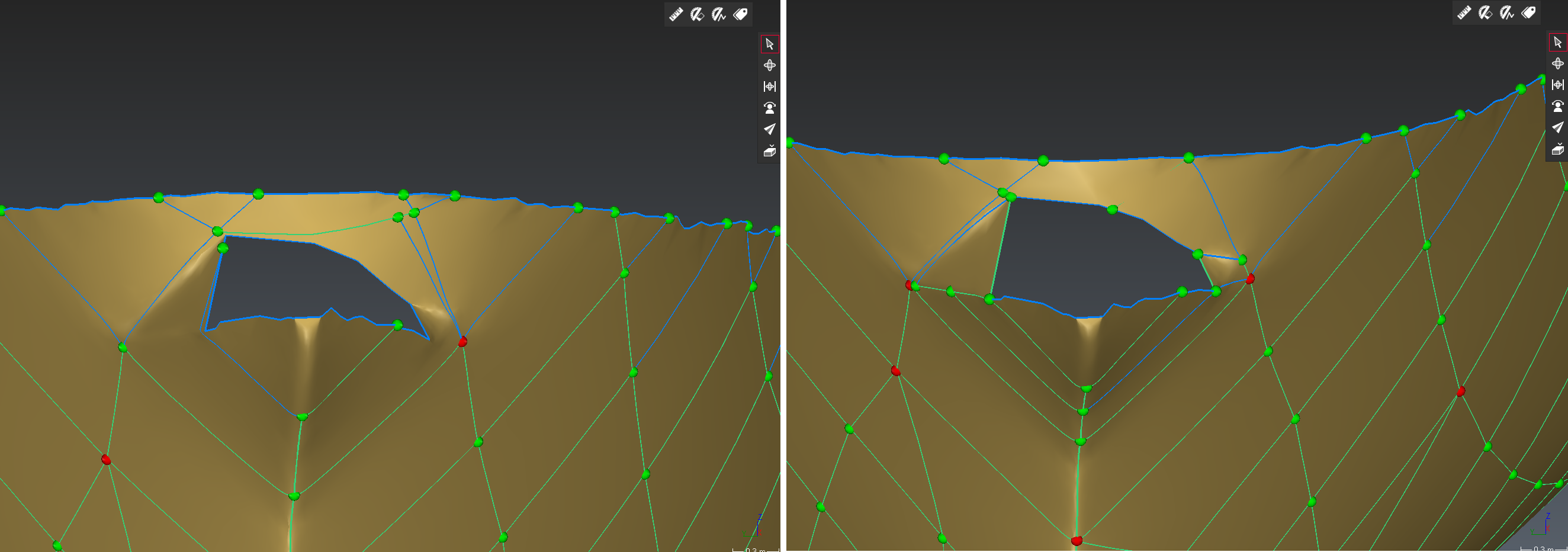 Edition of the bow (Before/After)
Generate a shell from the polyline network lying on the hull
Once the edition of the network is done, select it and the mesh, then launch Generate Patches.
A first result is automatically computed at startup.
The network polylines are approximated by CAD curves which serve as contour for CAD patched. Those patches are then fit on the hull.
You also have the possibility to edit the deviation of curves approximation to adjust the fitting.
Click on OK to validate the result.
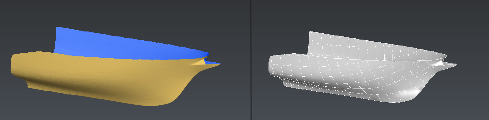
 Patch generation of the hull
Exporting the result
The hull shape is added to the document under the CAD Group in the object explorer.
You can inspect the number of faces from the properties.
You can also use it to make a 3D comparison with the original measurement mesh through Mesh vs CAD command.
To export it, select it then launch Export.
CAD shape can be exported to a lot of file format such as IGES, STEP, etc.